


Aquatic Industries, Inc.
7
1. This whirlpool is factory-assembled, complete with motor, pump, controls and plumbing. DO NOT lift or support
unit using plumbing lines or any part of circulation system. DO NOT relocate or otherwise modify any part of the
factory-installed circulation system, as this may affect the performance or safe operation of the whirlpool and will
void all warranties.
2. Inspect whirlpool unit and circulation system carefully before installing. Water test the unit before installation. If any
damages or defects are observed, DO NOT INSTALL. Notify your dealer immediately.
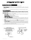
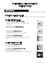
TO TEST:
PLACE THE TUB IN AN AREA WHERE IT MAY BE DRAINED AFTER TESTING.
3. Fill the tub with hot water (approximately 100
0
F) to the overflow and allow to stand for a few minutes.
4. Plug in pump cord and run pump for 10 minutes.
5. Inspect the tub completely. Any defect must be reported to Aquatic Industries, Inc. prior to installation in order to
have it covered by warranty.
6. Check to ensure that your installation will conform to all applicable codes and secure necessary permits. All electri-
cal and plumbing connections should be made by qualified electricians and plumbers.
7. This unit has been factory-tested prior to shipment for leakage and proper operation of the system. However,
in transit and handling, the half-unions on the suction and discharge ends of the pump may become loose. Make
sure these are hand-tight.
Aquatic will not be liable for any defects or damages, including incidental or consequential damages that could
have been discovered or prevented by following these procedures for storage, handling and inspection.
PRE-PLANNING ACCESS, PLUMBING AND ELECTRICAL INSTALLATION:
INSTALLATION
INSTRUCTIONS / GUIDELINES
READ ALL INSTRUCTIONS CAREFULLY BEFORE INSTALLATION
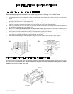
1. Sufficient clearance must be provided for access to service connections: motor, pump and electrical hook-ups.
(Minimum unobstructed access 16” x 16”)
A. Alcove Installation (with optional skirt): Access is provided by removing the skirt. To permit removal of skirt, allow
at least 6” clearance at both ends of tub: vanity, toilet, etc., must not obstruct skirt removal.
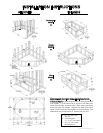
B. Island or Pier Installations: Provide access panel at motor end (see diagrams on page 9)
C. Sunken Installations: Provide access panel in floor or in ceiling below.
2. Drain/waste pipe stub must be located in wall or floor to match location of drain, waste and overflow
kit tee fitting. Provide a 6” x 12” box-out in sub-floor or slab (see diagrams on page 9).
3. When fittings (spout, handles, valves, etc.) are to be mounted on the unit, be certain that the hot and cold water copper
supply lines are located where there is ample room for mounting before setting the unit in place.
4. WARNING: When using electrical products, basic precautions should always be followed, including the
following:
A. DANGER: Risk of Electrical Shock. Connect only to a separate circuit protected by a Ground Fault Circuit
Interrupter (GFCI).
B. Connection. Electrical hook-up must be performed by a licensed electrician in accordance with local,
state and national electrical codes.
C. Access Panel Required. For built-in custom units, provide an access panel for servicing electrical
components (see Electrical Installation on page 8).
PRE-INSTALLATION PROCEDURES: