24
d. Mounting the Upper Unit
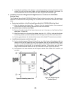
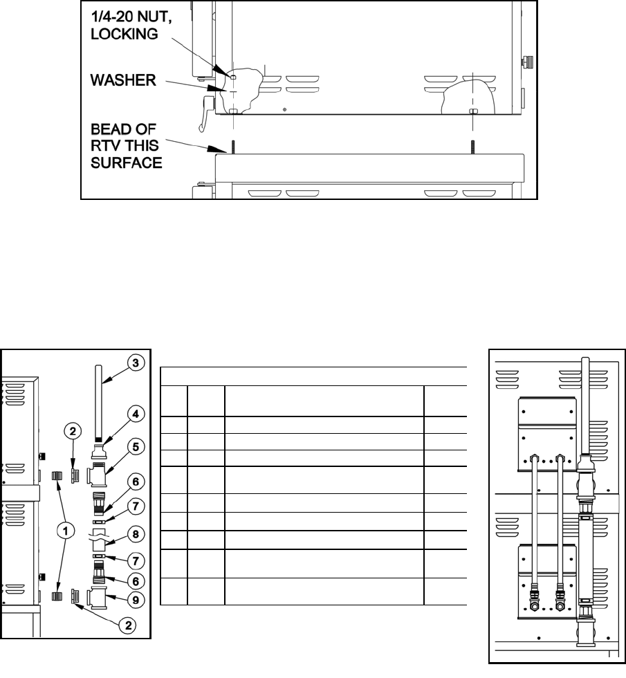
7). Before setting the upper steamer into place over the spacer studs, place a bead of RTV
around the edge of the entire spacer outline.
8). Remove the side panels from the upper unit and set it onto the spacer. The ¼-20 studs of the
spacer should go through the ½” welded nuts normally used to secure the legs to the
steamer.
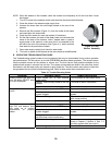
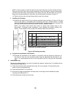
9). Secure the upper unit to the stand at the front pair of studs using the ¼-20 Lock Nut and
Washer provided (Figure 4-6).
e. Installing the Drain Between the Two Steamers
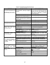
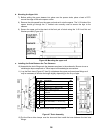
10).Assemble the drain fittings onto the steamers as shown in the schematic. Be sure to use a
suitable pipe dope compound or Teflon tape at all threaded pipe connections.
11). Lay the Drain hose (Figure 4-7 Item 8) out between the upper and lower hose fittings as it
may be necessary to shorten the length slightly depending on the fit-up of pipe
12).Put the Worm drive clamps over the hose and then install the hose between the two hose
fittings.
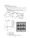
Figure 4-6 Mounting the upper unit
Drain Parts
Item
No.
Part
No.
Description Qty
1
14369 Nipple, 1” NPT, Close, Black Iron 2
2 02573 Bushing, Hex, 1 ½” NPT x 1” NPT 2
3 111008 Nipple, ¾” NPT x 14”, Toe 1
4 03616 Coupling, Reducing, 1 ½” NPT x ¾” NPT,
Black Iron
1
5 20220 Tee, 1 ½” NPT, Male Run, Black Iron 1
6 110985 Fitting, 1 ½” Hose x 1 ½” NPT(M), Plated 2
7 102018 Clamp, Hose, Worm Drive 2
8
110984
1300
Hose, Black EPDM, 1 ½” ID x 13” long 1
9 20221 Tee, 1 ½” NPT, Black Iron 1
Supplied with the steamer not part of the kit
Figure 4-7 Drain Assembly


