


PLANNING
GUIDE
Web: http://www.Dacor.com
Corporate Phone: 800-793-0093
Specifications are subject to change without notice.
See installation instructions for additional details.
2.1
24”, 27”, 30”, 36” Wide,
Warming Drawers
ERWD, EWD, IWD, MRWD, MWDV, MWDH,
OWD, PWD Warming Drawers
1/3
Revised
03/04/09
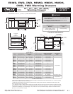
Warming Drawer
Cooktop
1 1/2" (38 mm)
Typical counter top
3/4” Min.*
(19 mm)
120 Vac
electrical
receptacle
A
36" Typ.
(914 mm)
B
C
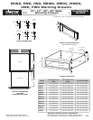
A
Warming Drawer
Warming Drawer
B
3/4" Min.*
(19 mm)
D
3/4" Min.*
(19 mm)
120 Vac
electrical
receptacle
36" Typ.
(914 mm)
C
C
27"/30"/36"
Dacor
single oven
Warming Drawer
Warming Drawer
Toe Kick
D
C
D
C
120 Vac
Elect.
120 Vac
Elect.
A
3/4" Min.*
(19 mm)
WARNING
1.
Observe all governing codes and ordinances during planning
and installation. Contact your local building department for
further information.
2.
This appliance must be installed in accordance with the
accompanying installation instructions.
All tolerances: +1/16”, -0, (+1.6mm, -0) unless otherwise stated
Model (A) Cutout Width
(B) Min. Width to
Adjacent Doors/
Drawers
(C) Cutout Height
(D) Min. Vertical Gap
Between Cutouts
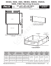
Min. Cutout
Depth
ERWD30 28 1/2” (724 mm) 30 1/4” (768 mm) 9 1/8” (232 mm) 1 1/4” (32 mm)*
EWD24 22 1/2” (572 mm) 24 1/4” (616 mm)* 9 1/8” (232 mm) 1 1/4” (32 mm)*
24” (610 mm)
EWD27 25 1/2” (648 mm) 27 1/4” (692 mm)* 9 1/8” (232 mm) 1 1/4” (32 mm)*
EWD30 28 1/2” (724 mm) 30 1/4” (768 mm)* 9 1/8” (232 mm) 1 1/4” (32 mm)*
EWD36 34 1/2” (876 mm) 36 1/4” (921 mm)* 9 1/8” (232 mm) 1 1/4” (32 mm)*
IWD24 22 1/2” (572 mm) *** 9 1/8” (232 mm) ***
IWD27 25 1/2” (648 mm) *** 9 1/8” (232 mm) ***
IWD30 28 1/2” (724 mm) *** 9 1/8” (232 mm) ***
MRWD27 25 1/2” (648 mm) 27 1/4” (692 mm)* 9 1/8” (232 mm) 1 1/4” (32 mm)*
MRWD30 28 1/2” (724 mm) 30 1/4” (768 mm)* 9 1/8” (232 mm) 1 1/4” (32 mm)*
MWDH27 25 1/2” (648 mm) 27 1/4” (692 mm)* 9 1/8” (232 mm) 1 1/4” (32 mm)*
MWDH30 28 1/2” (724 mm) 30 1/4” (768 mm)* 9 1/8” (232 mm) 1 1/4” (32 mm)*
MWDV27 25 1/2” (648 mm) 27 1/4” (692 mm)* 9 1/8” (232 mm) 1 1/4” (32 mm)*
MWDV30 28 1/2” (724 mm) 30 1/4” (768 mm)* 9 1/8” (232 mm) 1 1/4” (32 mm)*
OWD24 22 5/8” (575 mm) 24 1/4” (616 mm)** 11 15/16” (303 mm) 3/4” (19 mm)** 20 1/8” (511 mm)
PWD27 25 1/2” (648 mm) 27 1/4” (692 mm)* 9 1/8” (232 mm) 1 1/4” (32 mm)*
24” (610 mm)
PWD30 28 1/2” (724 mm) 30 1/4” (768 mm)* 9 1/8” (232 mm) 1 1/4” (32 mm)*
CUTOUTS DIMENSIONS
* Bare minimum spacing to allow for ventilation and avoid scraping on EWD, MW and PWD series models. See *** below for spacing
for IWD series or OWD24 with custom front panel.
** OWD24 with optional factory front panel kit only. Bare minimum spacing shown to allow for ventilation and avoid scraping. Gap
above and below cutout is 3/4” minimum.
*** On IWD series models or OWD24 without optional front panel kit: Height and width of custom front panel must exceed the chassis
face dimensions on page 3 to cover face of unit. Dimension (B) above = custom front panel width + 1/4” (6 mm). Dimension (D) above
= [custom front panel height - (C) Cutout Height] + 1/4” (6 mm) or 3/4” (19 mm) whichever is larger. Gap above and below cutout is
(D)/2 or 3/4” (19 mm) whichever is larger.
Electrical Circuit
Required
Total Connected
Load
120 Vac, 60 Hz, 15 Amp
grounded, dedicated circuit
0.5 kW (4.0 Amp)
ELECTRICAL REQUIREMENTS