


1
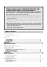
PRECAUTIONS TO BE OBSERVED BEFORE AND
DURING SERVICING TO AVOID POSSIBLE
EXPOSURE TO EXCESSIVE MICROWAVE ENERGY
(a) Do not operate or allow the oven to be operated with the door open.
(b) Make the following safety checks on all ovens to be serviced before activating the magnetron or other micro-
wave source, and make repairs as necessary: (1) Interlock operation, (2) Proper door closing, (3) Seal and
sealing surfaces (arcing, wear, and other damage), (4) Damage to or loosening of hinges and latches, (5)
Evidence of dropping or abuse.
(c) Before turning on power to the microwave oven for any service test or inspection within the microwave gen-
erating compartments, check the magnetron, wave guide or transmission line, and cavity for proper align-
ment, integrity, and connections.
(d) Any defective or misadjusted components in the interlock, monitor, door seal, and microwave generation
and transmission systems shall be repaired, replaced, or adjusted by procedures described in this manual
before the oven is released to the owner.
(e) A microwave leakage check to verify compliance with the Federal performance standard should be per-
formed on each oven prior to release to the owner.
TABLE OF CONTENTS
SAFETY AND PRECAUTIONS ...........................................................................................................................................2
1. FOR SAFE OPERATION ..................................................................................................................................2
2. FOR SAFE SERVICE PROCEDURES .............................................................................................................2
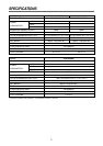
SPECIFICATIONS ...............................................................................................................................................................3
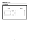
EXTERNAL VIEW................................................................................................................................................................4
1. OUTER DIMENSION.........................................................................................................................................4
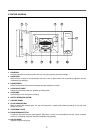
2. FEATURE DIAGRAM........................................................................................................................................5
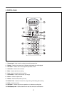
3. CONTROL PANEL ............................................................................................................................................6
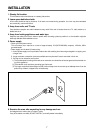
INSTALLATION...................................................................................................................................................................7
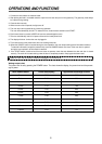
OPERATIONS AND FUNCTIONS.......................................................................................................................................8
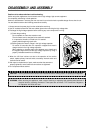
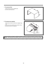
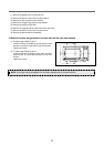
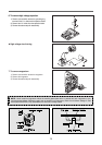
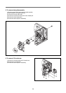
DISASSEMBLY AND ASSEMBLY......................................................................................................................................9
INTERLOCK MECHANISM AND ADJUSTMENT.............................................................................................................16
TROUBLE SHOOTING GUIDE .........................................................................................................................................17
MEASUREMENT AND TEST ............................................................................................................................................21
1. MEASUREMENT OF THE MICROWAVE POWER OUTPUT ........................................................................21
2. MICROWAVE RADIATION TEST ...................................................................................................................22
3. COMPONENT TEST PROCEDURE...............................................................................................................23
WIRING DIAGRAM............................................................................................................................................................24
PRINTED CIRCUIT BOARD..............................................................................................................................................26
1. CIRCUIT CHECK PROCEDURE ....................................................................................................................26
2. PCB CIRCUIT DIAGRAM................................................................................................................................29
3. P.C.B. LOCATION NO ....................................................................................................................................30
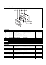
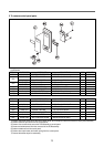
EXPLODED VIEW AND PARTS LIST...............................................................................................................................33
1. DOOR ASSEMBLY .........................................................................................................................................33
2. CONTROL PANEL ASSEMBLY......................................................................................................................33
3. TOTAL ASSEMBLY.........................................................................................................................................33