


4
WALL MOUNT FULL BACKGUARD INSTALLATION
RECOMMENDED INSTALLATION ORDER:
1) VENT HOOD 2)BACKGUARD SYSTEM 3) RANGE
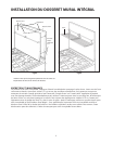
1. Locate and level range per installation instructions.
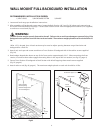
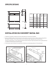
2. After unpacking all backguard system parts, locate the Back Section 1/8” (see fig. 03) above and centered over
the Island Trim attached to the range.* Secure Back Section to wall with the appropriate fasteners (not supplied)
to anchors or wood stud (fig. 03).
WARNING:
The Back Section must be securely fastened to the wall. Failure to do so could cause damage or personal injury if the
Backguard was to pull free from wall when racks are loaded. The maximum weight placed on each rack should be 10
lbs.
*After 1/8” is located, slots in back section may be used to adjust spacing between range island trim and
backguard for a flush fit.
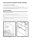
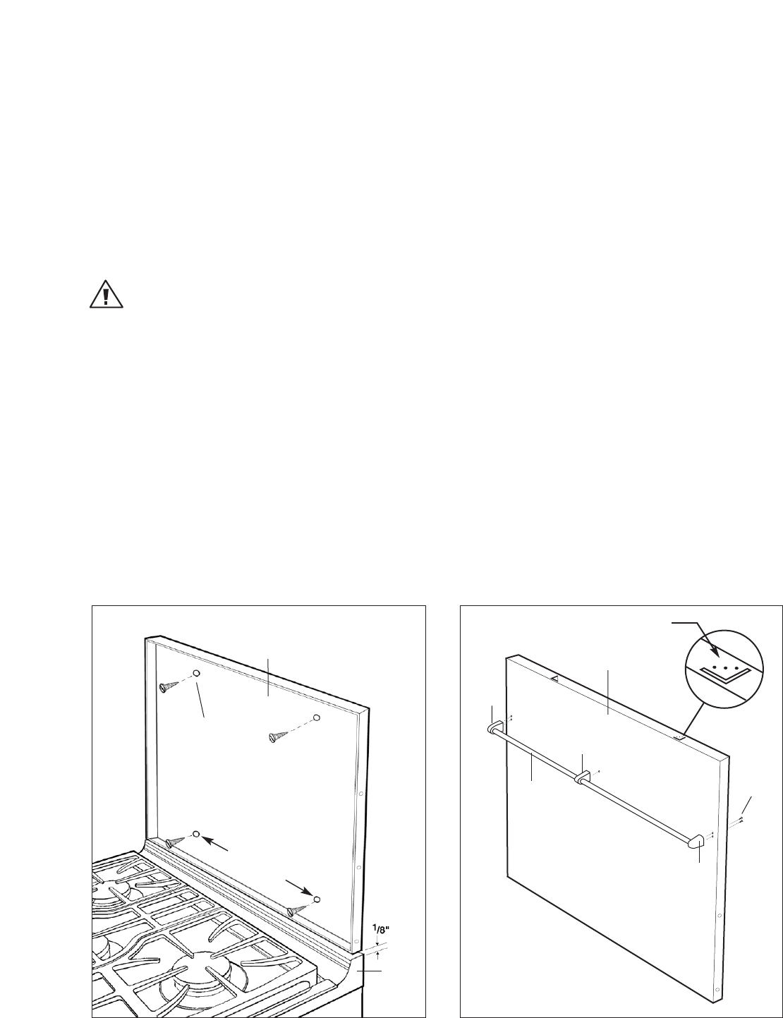
3. Attach rod, end caps and center stanchion to Front Section of backguard with #10 machine screws supplied
(fig. 04).
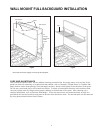
4. Bend wedge-shaped tabs down on top of the front section approximately 3/16”. When mounting the front
section, insure that these tabs engage the mating holes in the top of the rear section (see fig. 05, page 4).
5. Secure Front Section of backguard to Back Section with #8 self-tapping sheet metal screws supplied
(fig. 05, page 4).
6. Attach racks to rod (fig. 06, page 4). The maximum weight placed on each rack should be 10 lbs.
Fig.03
Fig.04
#10
Machine
Screws
Back Section
Island
Trim
Front Section
End
Cap
End
Cap
Center
Stanchion
Rod
Slots to choose
desired spacing
between Range Island
Trim and Backguard.
Bend down approx. 3/16”
16” for 30”
36” for 36/48”