1
HIGH SPEED OVEN INSTALLATION INSTRUCTIONS
INSTALLATION AND SERVICE MUST BE PERFORMED BY A QUALIFIED INSTALLER.
IMPORTANT: SAVE FOR LOCAL ELECTRICAL INSPECTOR'S USE.
READ AND SAVE THESE INSTRUCTIONS FOR FUTURE REFERENCE.
The electrical requirements for this oven are 240 volts, 15 amps.
The oven has a 6-15 plug and requires a 6-15 receptacle.
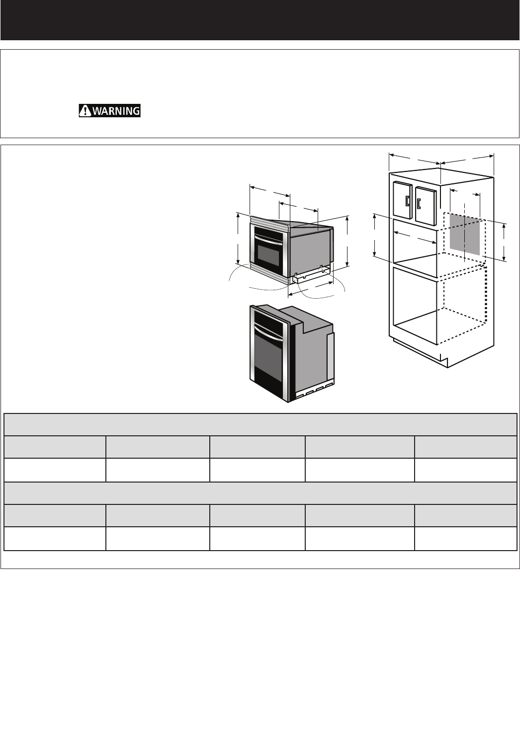
Figure 1
TINSEB424MRR0
All dimensions are in inches (cm).
NOTE:
1. Base must be capable of supporting 200
pounds (90.7 kg).
2. Make sure base is level and front of cabinet
is square. If the cabinet base is not level, the
oven will tend to slide out when opening
the door.
3. Minimum required distance is 36" (91.44
cm) from the floor.
4. At the rear of the opening, provide a 3
pronged, polarized, electrical outlet, 240
volt A.C., 15 amp. or larger. This outlet
should not be located in the shaded area
of Figure 1. It is exceedingly important that
the outlet be 240 volts and 15 amps. for
optimum oven performance.
5. Minimum required distance between the
high speed oven and the wall oven should
be 3-inches.
Printed in United States
PRODUCT DIMENSIONS
MODEL A B C D
30" (76.2) High Speed
Oven
30" (76.2) 22
27
/
32
" (58.0) 21
1
/
4
"
(54.0) 22
15
/
16
" (58.2)
CUTOUT DIMENSIONS AND CABINET WIDTH
MODEL Min. F Max. G Min. H Max. I
30" (76.2) High Speed
Oven
22
3
/
8
" (56.8) 22
5
/
8
" (57.5) 24" (61.0) min. 21
11
/
16
"(55.1) 21
15
/
16
"(55.7) 30" (76.2) min.
Important Notes to the Installer
1. Read all instructions contained in these installation
instructions before installing the high speed oven.
2. Remove all packing material from the oven compartments
before connecting the electrical supply to the high speed
oven. Remove the 2 shipping duct supports (see figure
1) by removing the 4 screws securing them. Reinsert 2
screws (each side) to secure the stainless cover.
3. Observe all governing codes and ordinances.
4. Be sure to leave these instructions with the consumer.
Important Note to the Consumer
Keep these instructions with your Owner's Guide for future
reference.
B
A
(53.9cm)
21
7
/32"
16
3
/4"
20
1
/4"
D
C
F
I
H
G
Remove2duct
shippingsupports
(bothsides)
C
L
Replacethese
screwsafter
shippingsupport
removal(bothsides)


