


Freestanding Direct
Vent Kit With Coupler
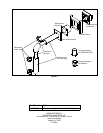
KIT COMPONENTS:
Quantity Description Quantity Description
1 Horizontal direct vent termination cap 1 Ø6” (17 cm) 90° elbow
2 Flue collar adapters (only one used) 4 Wire spacers
4 T-20 Torx screws 3 Decorative rings
1 Wall thimble 1 4 oz tube RTV silicone
1 Inside nish trim collar 20
9
/16” tech screws
1 5’ (190 cm) length of Ø4” (10 cm) double walled ex pipe 8 1” wood screws
2 24” (61 cm) section of Ø6” (17 cm) straight pipe 1 Vinyl siding deector
Please ensure that all components are supplied with this kit. If components are missing or have
been damaged, contact your dealer, distributor, or courier company. Do not attempt the installation if
components are missing or damaged.
INSTALLATION INSTRUCTIONS:
1. Decide on a location for the unit that will meet any or all local code requirements. Refer to the sections
in your owner’s manual on where to locating your stove, planning your installation and clearances to
combustibles.
2. Set the appliance in the desired location. Determine if any wall studs, electrical wiring, or plumbing
pipes are in the way of the venting system as it passes through the wall. If obstructions are found in
the wall it may be required to adjust the location of the appliance.
3. Set the appliance in the desired location. Temporarily place a 24” (61 cm) section with the non-crimped
end on the unit
4. Install the 90° elbow onto the vertical pipe on the stove pointing in the
direction that the vent will exit the structure.
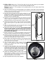
5. Project a level line from the center point of the elbow. Using this center
point, scribe a 10” (25.4 cm) hole or square on the wall . Cut the hole
out on both the interior and exterior wall surface.
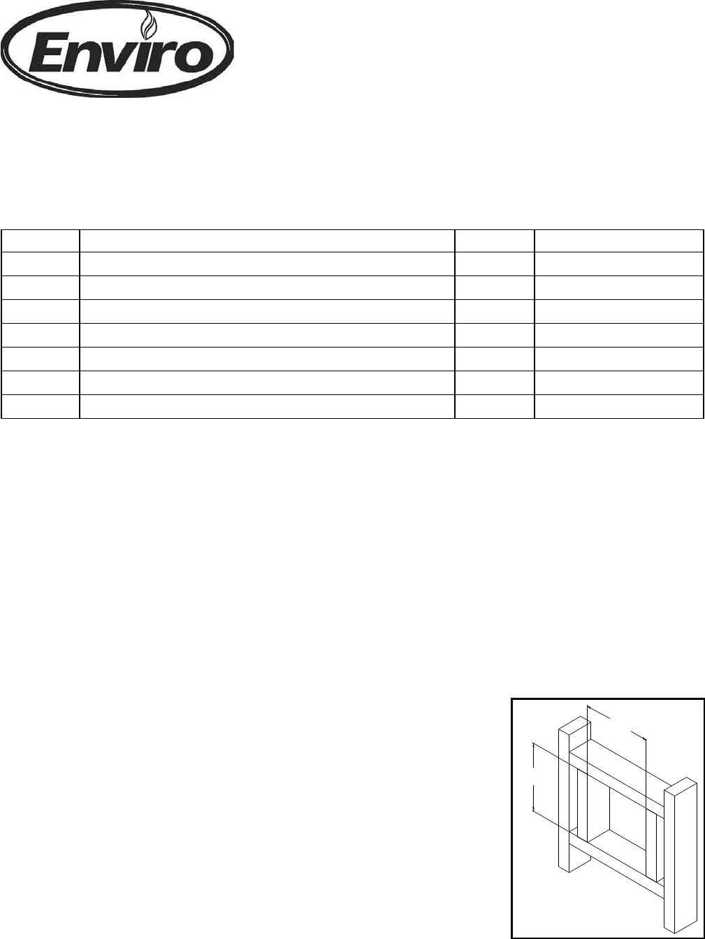
6. Frame the hole as shown in Figure 1.
7. Install the wall thimble and secure the thimble to the inner wall
surface.
8. With the appliance still in place install the 24” (61 cm) horizontal section
on the elbow and let this section of pipe protrude through the exterior
surface. Mark the pipe so that when it is cut it will be ush with the
exterior wall.
9. Dismantle the outer pipe sections.
Figure 1
Please read and understand these instructions before installing. Failure to follow
these instructions carefully could cause property damage or personal injury.