1
IMPORTANT:
Go to www.extron.com for the complete
user guide, installation instructions, and
specifications before connecting the
product to the power source.
MPS602 Series • Setup Guide
This guide provides basic instructions for an experienced technician to install, set up, and operate the Extron Media Presentation
Switcher, MPS602. Installation and service must be performed by authorized personnel only. For additional information and
specications, see the MPS602 product page at www.extron.com.
Step 1 — Disconnect Power and Mount the MPS602
Disconnect power to the MPS602 and turn off all devices that will be connected to it. The MPS602 is housed in a full rack width,
8.5 inch deep, 1U high metal enclosure that can sit on a table with the provided rubber feet or can be rack mounted. Select a
suitable mounting location, choose an appropriate mounting option, and follow the instructions provided with the mounting kit.
Step 2 — Cable the Switcher
L
R
SIG LINK
DTP IN
SIG LINK
DTP OUT
50/60 Hz
100-240V 1.0A MAX
1
2
RGB OUT
HDMI
MIC
MIX
RS-232
MPS 602 SA
Tx Rx G
MUTE HDMI AUDIO
PHANTOM POWER
SELECT
3
4
5
6
OUTPUTS
AMP OUT REMOTE
OVER DTP
OVER DTP
RS-232 IR
Rx GTx Tx Rx
RS-232 IR
Rx GTx Tx Rx
CLASS 2 WIRING
8Ω / 4Ω
INPUTS
AUDIO IN
AUDIO OUT
L 1 R L 2 R L 3 R
L VARIABLE R
L FIXED R
L 4 R L 5 R MIC LINE
R
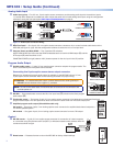
Figure 1. MPS602SA Rear Panel
a
AC power — Connect to standard AC power: 100-240 VAC, at 50-60 Hz
Video
b
RGB/VGA video input group — Two female 15-pin HD connectors for VGA input (numbered 1 and 2 on the rear panel). The
connectors accept VGA signals.
NOTE: The MPS602 does not scale or convert video, however it does convert an analog RGB/VGA input to digital
for digital output. The output signal resolution is the same as the input resolution.
c
RGB video output — One 15-pin HD connector acting as a pass-through to output the selected RGB/VGA input.
d
HDMI video input group — Three HDMI connectors for HDMI compliant audio and video input (numbered 3, 4, and 5 on the
rear panel). Connect to any HDMI source device using standard HDMI cable.
e
HDMI video output — Connect an HDMI display device for output from the selected HDMI input (
d
).
DTP
f
DTP In — Connect a DTP 230 source (Tx) to this RJ-45 jack (numbered 6 on the rear panel). The DTP input includes the
HDMI (or DVI) video with embedded audio, bi-directional RS-232 and IR, separate balanced/unbalanced analog audio,
and remote power for a connected DTP Tx device (see Twisted Pair Recommendations for DTP Communication on
page4).
g
RS-232 and IR (Over DTP) In — One 3.5mm 5-pole captive screw connector provides connection for bi-directional RS-232
and remote IR signals between the DTPTx connected to input 6 (
f
) of the MPS602.
h
RS-232 and IR (Over DTP) Out — One 3.5mm 5-pole captive screw connector to connect and pass bi-directional RS-232
and IR between the MPS602 and DTP230 Rx.
RS-232 and IR Over DTP Wiring
To pass bidirectional serial command signals between DTP-compatible devices, connect a control device to the three
leftmost poles (Tx, Rx, and G) of the 5-pole captive screw connector.
NOTE: RS-232 and IR data can be transmitted or received simultaneously.
i
DTP output — Connect an Extron DTP 230 receiver (Rx) using this RJ-45 jack. The DTP 230 signal format and protocol is
used. The output can include HDMI (with embedded audio), bi-directional RS-232 and IR, separate analog audio (from the
xed audio output), and remote power for a connected DTP230 receiver.
j
DTP out or HDMI out selection switch — One single-pole double-throw switch to select which output, DTP (
i
) or HDMI
(
e
) is active.