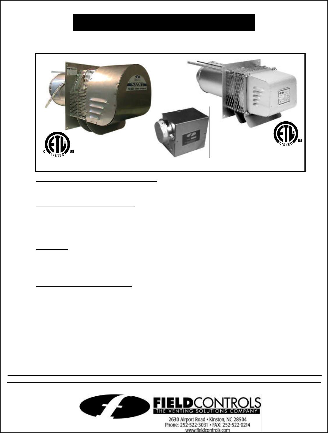
SIDEWALL POWER VENTER KIT
Model: SWG, SWGII & SWG Stainless Series
*Patented
TYPICAL VENTING SYSTEM COMPONENTS
1 - SWG Series Power Venter
1 - CK Series Control Kit (sold separately)
OPTIONAL SYSTEM COMPONENTS
SWG SERIES THROUGH-WALL EXTENSION KIT
For installation in wall thickness over 8 inches. Models PEK-4 through PEK-8 are available.
FOR MOST MULTIPLE HEATING EQUIPMENT SYSTEMS
One CK Series Control Kit for each appliance. Except for a 24V gas furnace or boiler and a
30mV water heater multiple venting system, use the CK-90 Series Control Kit.
CONTENTS
Available Control Kits.................................... 2 Maintenance.............................................8
Installation Instructions ................................. 2 General Inspection ...................................8
Wiring............................................................ 7 Repair Parts..............................................9
Air Flow Adjustments .................................... 7 System Information ................................11
GENERAL SYSTEM INFORMATION
Designed for operation with natural gas, LP gas and #2 fuel oil appliances.
1. The thermostat (wall thermostat or aquastat) calls for heat and energizes a relay which activates
the power venter. After the venter motor has come up to speed, the pressure switch closes. This
closes the circuit to the burner and allows the burner to fire.
2. For millivolt controlled water heaters using the CK-20 Series Control Kit, the gas valve pressure
switch activates the power venter at the same time as the burner fires.
3. After the heating requirement has been satisfied, the thermostat circuit will open and de-activate
the burner and power venter circuit.
4. For venting systems equipped with a post purge device, the power venter operates for a period
of time after the burner has shut off to purge remaining flue gases.
DO NOT DESTROY
THESE INSTRUCTIONS MUST REMAIN WITH EQUIPMENT
sold separately


