


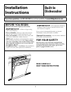

Installation Instructions
9
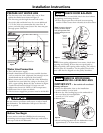
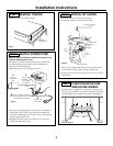
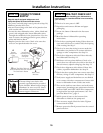
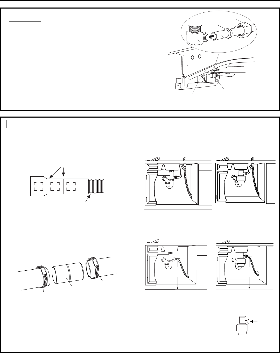
STEP 13 CONNECT WATER SUPPLY
Connect water supply line to 90° elbow.
• Slide compression nut, then ferrule over end of
water line.
• Insert water line into 90° elbow.
• Slide ferrule against elbow and secure with compres-
sion nut.
IMPORTANT: Check to be sure that door spring
does not rub or contact the fill hose or water supply
line. Test by opening and closing the door. Re-route the
lines if necessary.
Figure V
90° Elbow
Ferrule
90° Elbow
Hot Water
Supply Line
Compression Nut
Door Spring
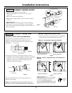
• If a longer drain hose is required, add up to 42" of
length for a total of 10 ft. length to the factory installed
hose. Use 5/8" or 7/8" inside diameter hose and a
coupler to connect the two hose ends. Secure the
connection with hose clamps.
Figure W
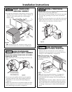
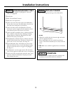
STEP 14 CONNECT DRAIN LINE
FOLLOW ALL LOCAL CODES AND ORDINANCES.
The drain hose molded end will fit 5/8", 3/4" or 1"
diameter connections on the air gap, waste tee or
disposer. Cut on the marked line as required for your
installation.
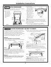
DRAIN LINE INSTALLATION
• Connect drain line to air gap, waste tee or disposer
using either previously determined method.
Waste Tee Installation
Method 1 – Air gap with waste tee or disposer
Disposer Installation
Waste Tee Installation
Method 2 – Built-in “High drain loop” with waste tee or
disposer
Disposer Installation
Figure Y
Figure Z
• Secure the drain hose to the air gap, waste tee or
disposer with clamps.
Note: TOTAL DRAIN HOSE LENGTH MUST NOT
EXCEED 10 FEET FOR PROPER DRAIN OPERATION.
IMPORTANT: When connecting
drain line to disposer, check to be
sure that drain plug has been
removed. DISHWASHER WILL NOT
DRAIN IF PLUG IS LEFT IN PLACE.
Cutting Lines
1"
3/4"
5/8"
IMPORTANT: Do not cut corrugated
portion of hose
Remove
Hopper
Plug
Figure X
Hose Clamp
Coupler
Hose Clamp
18"
Min.
18"
Min.