


For answers to your Monogram,
®
GE Profile
™
or
GE
®
appliance questions, visit our website at
ge.com or call GE Answer Center
®
service,
800.626.2000.
PS900SP
GE Profile
™
30" Slide-In Electric Range
Specification Created 5/09
220439
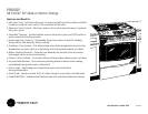
All GE ranges are equipped with
an Anti-Tip device. The installation
of this device is an important,
required step in the installation
of the range.
Listed by
Underwriters
Laboratories
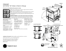
Dimensions and Installation Information (in inches)
28-1/4*
36
Maintain
at least 6"
from nearest
combustible
surface.
Acceptable
Electrical
Outlet Area
30" Slide-In Range
Dimensions (in inches)
45-1/8
2-1/4
5
6
4-1/2
30
30" Min.
15" Min.
6
30" Slide-in Elec. Range
Aug. 8, 2003 -km
23-3/16
30
30
If you are NOT using the
Filler strip or Backguard:
If you are using the
Filler strip or Backguard:
25
*Wall to front of
closed door handle
on model JSP34.
28" on models
JSP26/JSS26/16.
Note: Range may be placed with 0" clearance (flush) at the back wall and side walls
below countertop if the range side trims above the countertop extend beyond the cabinet
fronts at least 1/4". (Self-clean models only.) Maintain at least 6" distance from nearest
combustible surface.
30
31-1/2
Note: Cabinets installed adjacent to slide-in ranges must have an adhesion
spec of at least 194° temperature rating.
Note: To reduce the possibility of scorching the side walls above the countertop
when no load is present on burners, it is recommended that a minimum 6"
spacing from adjacent side wall be allowed for possible extended high-heat ele-
ment operation.
Receptacle Locations: For all 30" Slide-In Ranges locally approved flexible
service cord or conduit must be used because terminals are not accessible
after range installation.
See shaded area in drawing for location of electrical
outlet box. Recommended
outlet locations allow range to be installed directly against rear wall.
KW Rating
240V
11.6
208V
8.7
Breaker Size
240V
40 Amps
208V
40 Amps
Installation information: Before installing, consult installation instructions
packed with product for current dimensional data.
Optional Kits For Slide-In
Electric Ranges
(Available At Additional Cost)
Accessory Backguards
(Attaches to the back of range
as a backguard when unit is
installed in 30" free-standing
cutout)
JXS32SS (Stainless) - 4" High
JXS32WW (White) - 4" High
JXS32BB (Black) - 4" High
JXS37WW (White) - 5-1/4" High
JXS37CC (Bisque) - 5-1/4" High
JXS37BB (Black) - 5-1/4" High
Body Sides
(Slide-in ranges are sold
without sides installed. Can
be installed on either left
or right when unit has one
exposed side [no cabinet
adjacent]. Kit contains
1 body side)
JXS77WW (White)
JXS77BB (Black)
Rear Filler Strip
WB07T10680 - Black Filler Strip Assembly
Optional Lower Trim Kits
(If counter height is greater
than 36.5", a lower trim kit
is recommended to extend
the useful height to 38"
maximum)
JXS56WW – White
JXS56BB – Black
Acceptable
Electrical
Outlet Area
30" Min.
30" Min.
Shave Raised Edge To Clear
31-1/8" Wide Control Panel
Excluding Models JSS28 and JSP39
2-7/8"
To Front
Surface Of
Countertop
20-5/8" Door
Clearance
From Front
Surface of
Countertop
31-1/4
30
25-3/4**
Recommended
6" Min.
From Walls
23-3/16
15" Min.
A/B*
13" Max.
2-1/2
30
25
9/16
7-1/2
2-1/2
Accessory
Backguard
24
36-1/4
*JXS37 is 5-1/4" and JXS32 is 4"
(excluding handle)
**Total depth from wall to
front of closed oven door
including handle is 27-13/16.
35-7/8"–38"
from floor to
countertop
If the countertop area is not flat, excess tension may be applied to the glass cooktop causing breakage
and voiding the warranty. Make sure the wall covering, countertop, flooring and cabinets around the range
can withstand the heat (up to 200˚F) generated by the range.
A. Allow 30
"
minimum clearance between surface units and bottom of unprotected wood or metal cabinet,
or allow a 24
"
minimum when bottom of wood or metal cabinet is protected by no less then 1/4
"
thick
flame retardant millboard covered with no less than No. 28 MSG sheet metal (.015
"
thick), .015
"
thick
stainless steel, .025
"
aluminum or .020
"
copper.
B. This appliance has been approved for 0
"
spacing to adjacent surfaces above the cooktop. However,
a minimum 6
"
spacing to surfaces less than 15
"
above the cooktop and adjacent cabinetry
is recommended to reduce exposure to steam, grease splatter and heat. Allow 1/4
"
minimum clearance
at the back wall.
To reduce the risk of burns or fire when reaching over hot surface elements, cabinet storage space above
the cooktop should be avoided. If cabinet storage space is to be provided above the cooktop, the risk can
be reduced by installing a range hood that projects at least 5
"
beyond the front of the cabinets. Cabinets
installed above the cooktop must be no deeper than 13
"
.