


1
/
2
in. UL Classified
Gypsum Wallboard (see
UL Rated Wall Design
for Additional Details)
2
1
/
2
in. Min.
Stud or Runner
Damper
Sleeve
Angle Fastener
(see Note 2)
1
1
⁄2 in. x 2
1
⁄2 in.
16 ga. angle
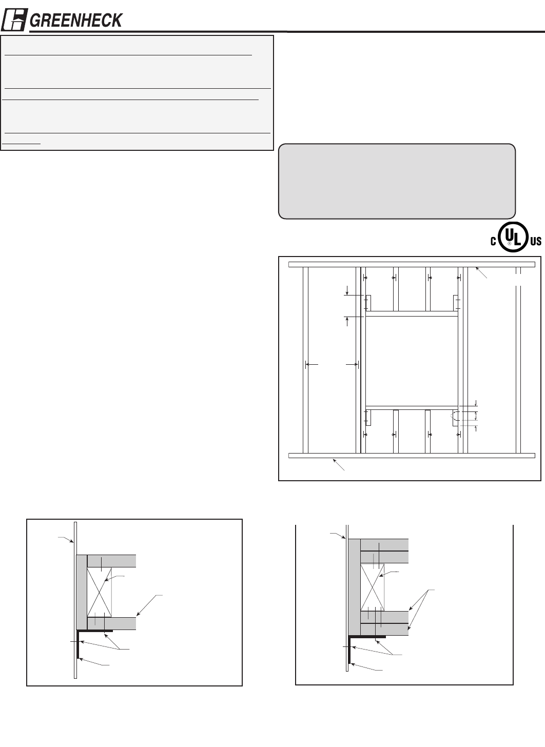
Figure #2: 1 Hour Wall Rating
1
/2 in. UL Classified
Gypsum Wallboard (see
UL Rated Wall Design
for Additional Details)
2
1
/2 in. Min.
Stud or Runner
Damper
Sleeve
Angle Fastener
(see Note 2)
1
1
⁄2 in. x 2
1
⁄2 in. 16
ga. angle
Figure #3: 2 Hour Wall Rating
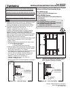
Figure #1: Opening Preparation Detail (double vertical
studs are not required for openings 36 in. x
36 in. [914mm x 914mm] or smaller)
12 in.
24 in. o.c.
Maximum
Floor Runner
2 in.
Ceiling Runner
2 Panhead
Screws
24 in. o.c.
Maximum
(metal studs)
24 in. o.c.
Maximum
(metal studs)
16 in. o.c.
Maximum
(wood studs)
16 in. o.c.
Maximum
(wood studs)
2 in.
Notes
1. Gypsum panels must be screwed 12 in. (305mm) on center
maximum to all stud and runner flanges surrounding
opening. (See Figure 1 for Opening Preparation Details).
2. Fire damper and sleeve assemblies 80 in. W x 50 in. H
(2032mm x 1270mm), 50 in. W x 80 in. H
(1270mm x 2032mm), or 40 in. W x 100 in. H
(1016mm x 2540mm) and smaller only require retaining
angles on one side of the partition. (See Figure 2 and
Figure 3). Retaining angles must be attached to the
sleeve and the partition. Larger damper assemblies require
retaining angles on both sides of the partition. Retaining
angles must be attached to the sleeve.
•Retaininganglesmustbeaminimumof16gauge(1.5mm)
steel and have a minimum of 1
1
/2 in. x 2
1
/2 in. legs
(38mm x 63mm).
•Retaininganglesmustbeattachedtothesleeveusing
one of the methods shown below:
• tackorspotwelds
• #10sheetmetalscrewsandbolts
•Retaininganglesmustbeattachedtothepartitionusing
drywall screws of a length such that the screw engages
the stud by a minimum of 1
3
/4 in. (44mm)
•Aminimumoftwoconnectionsperside,top,andbottom,
12 in. (305mm) O.C. maximum for openings of
48 in. W x 36 in. H (1219mm x 914mm) and less, and
6 in. (152mm) O.C. for openings 80 in. W x 50 in. H
(2032mm x 1270mm), 50 in. W x 80 in. H,
(1270mm x 2032mm) and 40 in. W x 100 in. H
(1016mm x 2540mm)or less.
•Retaininganglesmustoverlapthepartitionaminimumof
1 in. (25mm)
Copyright©2008GreenheckFanCorporation
462102 Wood Stud Supplement
Rev. 4 March 2008
®
Part #462102
INSTALLATION INSTRUCTION SUPPLEMENT
Refer to:
‘Installation Instructions for FD, DFD, SSFD, & KFD Models’
(Part#452763)
or
‘Installation Instructions for FSD-XXX, DFD-XXX, & CFSD-XXX,
SSFSD-XXXSeriesFire&CombinationFireSmokeDampers’
(Part#461336)
or
‘Installation Instructions for FD & DFD 150X Series Curtain Fire
Dampers’(Part#453946)foradditionaldetails.
Wood Stud Framing for Fire Dampers in Drywall
Partitions Utilizing One Retaining Angle
FD & DFD Series
1
1
/2 Hour Curtain Fire Dampers and
FSD & SSFSD Series
1
1
/2 Hour Combination Fire Smoke Dampers
Vertical Mount
“UL CLASSIFIED
(see complete marking on product)”
“UL CLASSIFIED to Canadian safety standards
(see complete marking on product)”
Standards UL 555 & 555S
ClassificationsFiledatULunderListing#R13317