


Part number 463622
DFD, FD, FSD Series
Grille Installation
Installation Instruction Supplement
Refer to:
‘Installation Instructions for FD, DFD, SSFD Models Fire’
(Part #452763)
‘Installation Instructions for FSD-XXX, DFD-XXX, CFSD-XXX, &
SSFSD-XXX, Series Fire & Combination Fire Smoke Damper’
(Part #461336)
‘Installation Instructions for FD & DFD 150X Series Curtain Fire
Damper’ (Part #453946)
“UL CLASSIFIED
(see complete marking on product)”
“UL CLASSIFIED to Canadian safety standards
(see complete marking on product)”
Standards UL555 & UL555S
Classifications filed at UL under Listing #R13317
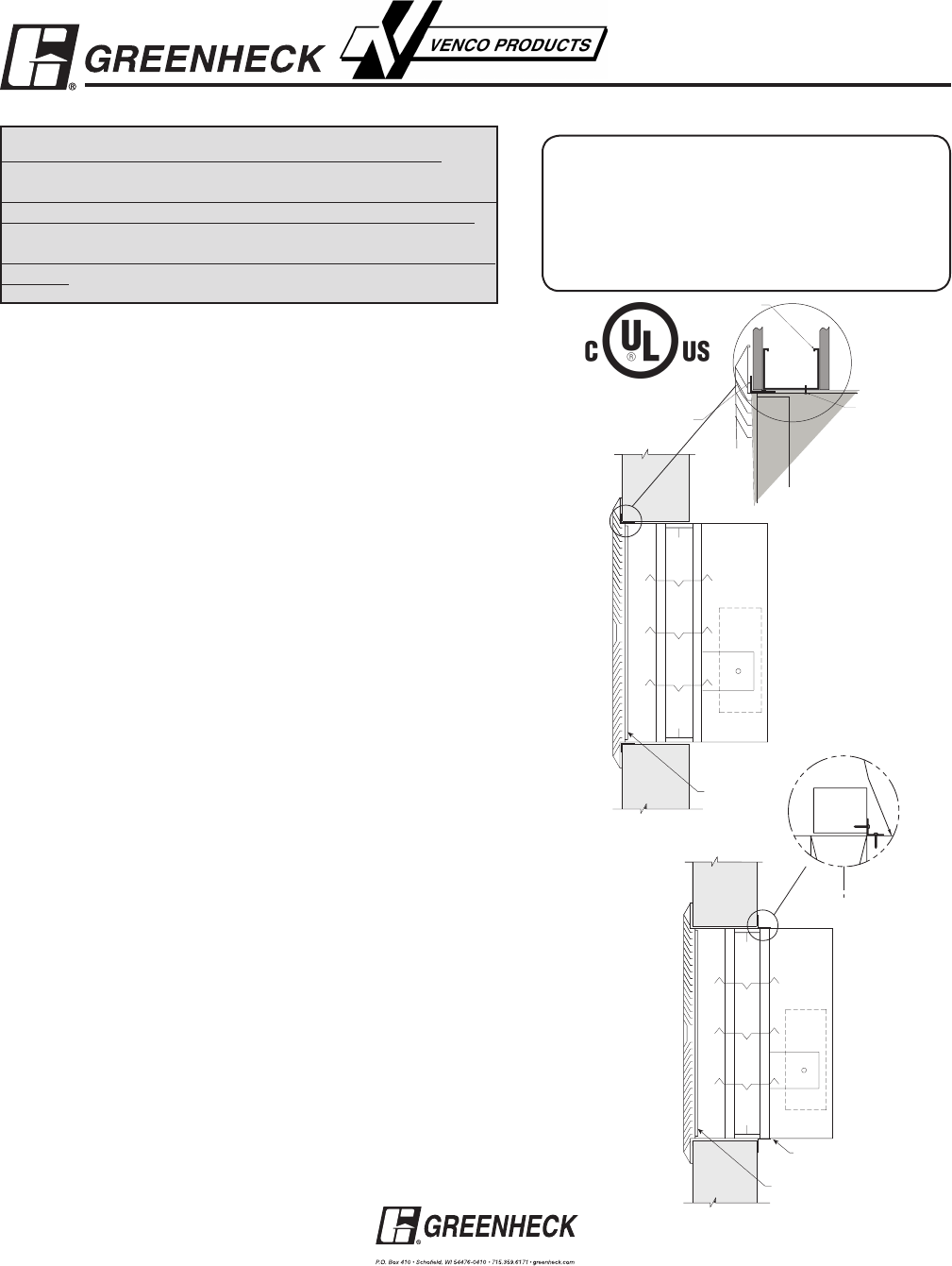
1
1
/2 in. x 1
1
/2 in.
16 ga. angles
(minimum)
Grille (supplied
by others)
Damper sleeve
Fig. 2
Copyright ©2007 Greenheck Fan Corporation
Grille Installation Supplement R3 July 2007
Clearance Requirements
There is no minimum clearance requirement between the wall opening and
the sleeve exterior. However, to facilitate installation, clearances between the
wall opening and the damper sleeve are recommended. Although there is no
maximum allowable clearance, a minimum overlap of ½ in. (13mm) between the
wall and the flange/retaining angle must be maintained.
1. Single Flange Method
Damper/sleeve assemblies must be installed in wall openings using flanges
and sheet metal screws as illustrated and describe below. This method is only
applicable to 1½ hour rated damper; the 3 hour damper and dampers larger than
36 in. x 36 in. (914mm x 914mm) will require a minimum of 1½ in. x 1½ in. (38mm
x 38mm) legs.
• Flange on front (grille end) of sleeve must be a minimum of 16 ga. (1.6mm)
steel and have a 5/8 in. minimum flange leg. Using #10 sheet metal screws,
screw from inside of sleeve through the rear portion of the studs (as shown
in Figure 1). Space screws a maximum of 6 in. (152mm) on center and a
maximum of 2 in. (51mm) from the corners (minimum of two screws per side).
No retaining angles are required on the side of wall opposite from the grille.
2. Retaining Angle Method
Damper/sleeve assemblies must be installed in wall and floor openings using
retaining angles on at least one side of the wall or floor as described below:
• Retaining angles must be a minimum of 16 ga. (1.6mm) and have a minimum of
1½ in. x 1½ in. (38mm x 38mm) legs (see Figure 2).
• For grille installation on fire damper up to 36 in. x 36 in. (914mm x 914mm)
maximum, angle legs may be reversed and one leg inserted into the wall/floor
opening providing the required clearance is maintained between angle leg
fastener and the wall/floor opening. Note: Screws used to attach grille are
allowed to penetrate reversed angle leg.
• Retaining angles must be attached to the damper using one or more of the
following methods of attachment (refer to label on outside of sleeve for ‘No
Screw’ area):
• Tack or spot welds
• #10 (¾ in. [19mm] max.) sheet metal screws
• ¼ in. (6mm) bolts and nuts
• 3/16 in. (4mm) steel pop rivets
A minimum of two connections per side, top and bottom, 12 in. (305mm) O.C.
maximum. The angles must be attached to all four sides of the sleeve. Ensure
that attachment device does not interfere with the operation of the damper and
the free movement of the damper blades. The angles need not be attached to
each other at the corners.
• Retaining angles must be attached to the partition using one of the methods
below (see single side retaining angle-vertical mount supplement part
#462099):
• Drywall screws of a length such that the screw engages the steel
stud/track by ½ in. (13mm) (steel framing).
• Drywall screws of a length such that the screw engages the wood
stud by 1¾ in. (44mm) (wood framing).
• Steel anchors or self tapping concrete screws penetrating masonry or
block 1¼ in. (31mm).
Grille (supplie d
by others)
Steel stud
5/8 in. x 1 in.
16 ga. angles
minimum
#10 sheet metal
screws spaced 6 in.
on center and a
maximum of 2 in.
from the corners
(minimum of 2
screws per side).
Screw into rear
portion of the studs
so as to avoid space
conflicts with the
grille assembly.
Fig. 1