


Part number 468502
Duct to Sleeve Connection
Refer to:
‘Installation Instructions for FD, DFD, SSFD, & KFD Series”
(Part number 452763)
or
“Installation Instructions for FSD-XXX, DFD-XXX, SSFSD-XXX &
CFSD-XXX Series Fire & Combination Fire Smoke Dampers’
(Part number 461336)
or
“Installation Instructions for FD & DFD 150X Series Curtain Fire
Dampers’ (Part number 453946)
or
“Installation Instructions for OFSD, ODFD, OFD, AND OSSFD
Series Dampers’ (Part number 461337)
or
‘Installation Instructions for FSD-3XXXV Series Dampers’
(Part number 461666) for additional details
INSTALLATION INSTRUCTION SUPPLEMENT
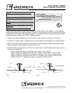
Spot weld or Tek screw per
manufacturer instructions
Spot weld or Tek screw pe
r
manufacturer instructions
Damper Sleeve
Damper Sleeve
Butyl Gasket
Butyl Gasket
TDC or TDF
Connection
TDC or TDF
Connection
Metal cleat
#10 x 3/4”
TEK Screw
These instructions describe an alternate breakaway connection between a fire damper or combination fire
smoke damper sleeve and an adjoining piece of ductwork. This alternate connection is covered under the UL
certification of the damper. These instructions apply to a connection between a manufactured flange system
by Ductmate, Ward, or Nexus and a TDC or TDF flange system.
1. Install the manufactured flange system onto the damper sleeve per the manufacturer’s instructions.
2. To seal the two flange systems together Neoprene or Butyl gasket may be applied to the mating surfaces.
3. Align the two flange systems together. An optional 3/8 in. (9mm) bolt may be used in the corners to help
with the alignment. These bolts do not have to be removed.
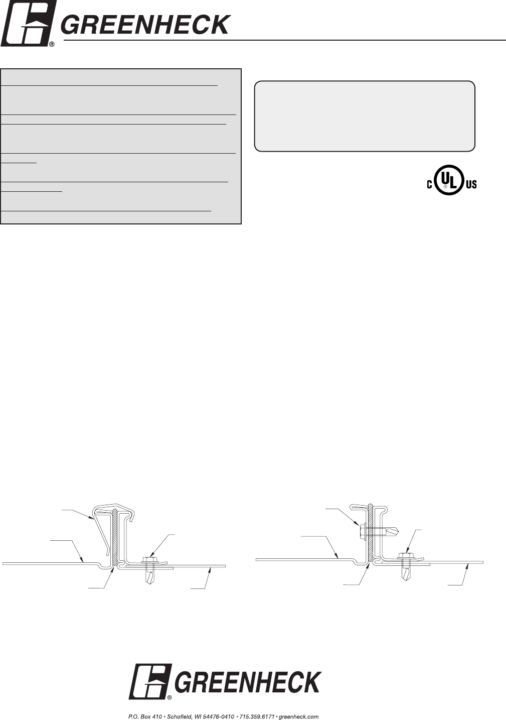
4. Install the metal cleat (see Figure 1) or #10 tek screw (see Figure 2), approximately equally spaced, per the
schedule described below:
• Width or height less than 24 in. (610mm); use one cleat or screw per side
• Width or height 24 in. (610mm) to less than 36 in. (914mm); use 2 cleats or screws per side
• Width or height 36 in. (914mm) to less than 54 in. (1372mm); use 3 cleats or screws per side
• Width or height 54 in. (1372mm) to less than 72 in. (1829mm); use 4 cleats or screws per side
• Width or height 72 in. (1829mm) or greater; use 5 cleats or screws per side.
Copyright © 2007 Greenheck Fan Corporation
468502 Breakaway connection Rev. 3 December 2007
Figure 1
Spot weld or Tek screw per
manufacturer instructions
Spot weld or Tek screw pe
r
manufacturer instructions
Damper Sleeve
Damper Sleeve
Butyl Gasket
Butyl Gasket
TDC or TDF
Connection
TDC or TDF
Connection
Metal cleat
#10 x 3/4”
TEK Screw
Figure 2
“UL CLASSIFIED
(see complete marking on product)”
“UL CLASSIFIED to Canadian safety standards
(see complete marking on product)”
Standards UL 555 & 555S
Classifications Filed at UL under Listing #R13317