


™
H-IM-79EJANUARY2011PartNo.25001401
Beacon II™
Refrigeration Systems
Installationand
OperationManual
Replaces H-IM-79E (09/07)
TableofContents
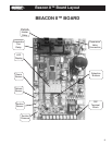
Beacon II™ Board Layout ........................................................ 3
Installation Tips ........................................................................ 4
Refrigerant Line Brazing ........................................................... 5
Power Supply ........................................................................... 5
Wiring ....................................................................................... 5
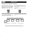
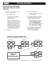
Multiple Evaporator Conguration ........................................... 6
Box Temperature Control Settings ........................................... 7
Leak Testing ............................................................................. 7
Refrigerant Charging ............................................................... 7
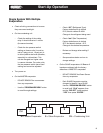
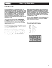
Start-Up Operation ..............................................................8-11
Operating Mode Display ......................................................... 11
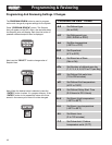
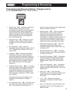
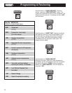
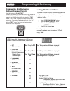
Programming and Reviewing Settings and Changes .......12-13
Program Review Button
Select Button
Enter Button
Monitoring Items .................................................................... 14
Monitor Button
Force Defrost Button
Force Service Button
Reset Time Button
Clear/Test Button
Locking The Beacon II Board ................................................. 15
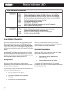
Status Indicator LED .........................................................15-16
Low Ambient Operation ......................................................... 16
Pumpdown ........................................................................16-17
Defrost ...............................................................................17-18
Alarms ................................................................................... 18
Error Indicator ......................................................................... 19
Checking Operation of Expansion Valve ...........................20-21
Power Failures ........................................................................ 21
Spare Sensor Terminals .......................................................... 21
Checking Sensors .................................................................. 21
Sensor Resistance/Temperature Table ................................... 22
System Defaults ..................................................................... 22
InterLink Replacement Parts List ........................................... 23
Operational Limits .................................................................. 23
Expansion Valve Capacity ...................................................... 24
Diagnostics ........................................................................24-27
Wiring Diagrams ................................................................28-33
Preventive Maintenance ......................................................... 34
Service Record ..................................................................35-36