


185211000 10
7. Install plug in end of water tank overflow tube.
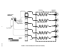
INSTALLING PRODUCT TANKS QUICK DISCONNECTS ON UNIT PRODUCT
INLET LINES
(see Figure 2)
NOTE: The numbered Unit product inlet lines are labeled to identify the dispensing valves they serve.
For example: Line labeled ‘‘1’’ must be connected to the product tank that provides product to be
dispensed from the No. 1 dispensing valve. (No. 1 dispensing valve is the valve on the right side when
facing front of the Unit).
If applicable, ADAPTER FITTINGS (item 1) may be used to lengthen the Unit product inlet lines to
locate product tanks remote from the Unit.
All Unit product inlet lines internal connections have been made at the factory. Install product tanks liquid quick
disconnects on ends of the Unit product inlet lines.
INSTALLING PRIMARY CO
2
REGULATOR ASS’Y AND CONNECTING
PRODUCT TANKS CO
2
LINES TO REGULATOR
(see applicable Figure 2)
WARNING: CO
2
displaces oxygen. Strict attention must be observed in the prevention of
CO
2
(carbon dioxide) gas leaks in the entire CO
2
and soft drink system. If a CO
2
gas leak is
suspected, particularly in a small area, immediately ventilate the contaminated area before
attempting to repair the leak. Personnel exposed to high concentration of CO
2
gas will experience
tremors which are followed rapidly by loss of consciousness and suffocation.
WARNING: To avoid personal injury and/or property damage, always secure CO
2
cylinder in
upright position with a safety chain to prevent it from falling over. Should the shutoff valve
become accidentally damaged or broken off, CO
2
cylinder can cause serious personal
injury.
1. Position CO
2
cylinder in upright position and secure with safety chain.
2. Install primary CO
2
regulator on CO
2
cylinder. MAKE SURE NYLON WASHER IS INSIDE REGULATOR
ASSEMBLY COUPLING NUT BEFORE INSTALLING ON CO
2
CYLINDER.
3. Connect made up product tanks CO
2
lines to check valves in primary CO
2
regulator assembly outlet
manifold. Seal connections with tapered white gaskets.
4. Install product tanks gas quick disconnects on ends of product tanks CO
2
lines. CO
2
lines should be
labeled for identification as to which product tanks they serve.
INSTALLING DISPENSING VALVE KNOBS
(see Figure 3)
Install KNOBS (item 2) on dispensing valves by pushing knobs down into place on the valve’s levers.
INSTALLING DISPENSING VALVE
DECAL KIT
Install DECAL KIT, DISPENSING VALVES KNOBS (item 6) on the dispensing valve’s knobs.
INSTALLING 5-INCH PLAQUES ON SIDES OF UNIT
If applicable, install PLAQUES, (item 5) on both sides of the Unit.