


185211000 18
6. Open (counterclockwise) CO
2
cylinder valve slightly to allow lines to slowly fill with gas, then open valve
fully to back-seat valve. (Back-seating valve prevents leakage around valve shaft).
7. Check CO
2
connections for leaks. Tighten any loose connections.
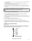
REPLENISHING PRODUCT SUPPLY
1. Remove inlet (CO
2
) disconnect (grey) and outlet disconnect (black) from empty product tank, then remove
tank.
2. Place full product tank in position, then connect inlet (CO
2
disconnect (grey) and outlet disconnect (black)
to the tank.
PRODUCT FLAVOR CHANGE
Sanitize applicable product system as instructed, then install full tank of new flavor product.
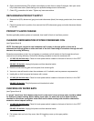
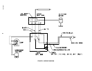
CLEANING REFRIGERATION SYSTEM CONDENSER COIL
(see Figures 3 and 4)
NOTE: Circulating air required to cool condenser coil is drawn in through grille on front and is
exhausted out through grilles on sides and back of the Unit. Restricting air circulation through Unit will
decrease its cooling efficiency.
Excessive accumulation of dust, lint, and grease on condenser coil will restrict air flow through the coil and
cause a loss of cooling efficiency. Perform the following procedure to clean the condenser coil.
1. 115 VAC, 60 Hz Units only– Place Unit main power switch, located on the back of the Unit, in the ‘‘OFF’’
(down) position.
230 VAC, 50 Hz Unit– Unplug Unit power cord from electrical outlet.
2. Remove screws securing grille on front panel, then remove grille.
3. Vacuum or use soft brush to clean the condenser coil. If available, use low-pressure compressed air.
4. Install grille on Unit front panel and secure with screws.
5. 115 VAC, 60 Hz Units only– Place Unit main power switch, located on the back of the Unit, in the ‘‘ON’’
(up) position.
230 VAC, 50 Hz Unit– Plug Unit power cord into electrical outlet.
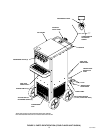
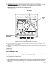
CHECKING ICE WATER BATH
(see Figures 3 and 4)
A ‘‘gurgle’’ heard from Unit indicates water level in water tank is low and more water should be added
for maximum product cooling. Before adding more water, ice water bath and ice bank should be
checked for cleanliness and agitator motor shaft and ice bank sensing bulb should be checked for
excessive mineral deposit build-up.
1. 115 VAC, 60 Hz Units only– Place Unit main power switch, located on the back of the Unit, in the ‘‘OFF’’
(down) position.
230 VAC, 50 Hz Unit– Unplug Unit power cord from electrical outlet.
2. Pull release latch on front of top cover, then lift hinged top cover up into open position.