


5
INSTALLATION STEPS
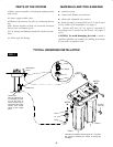
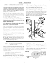
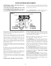
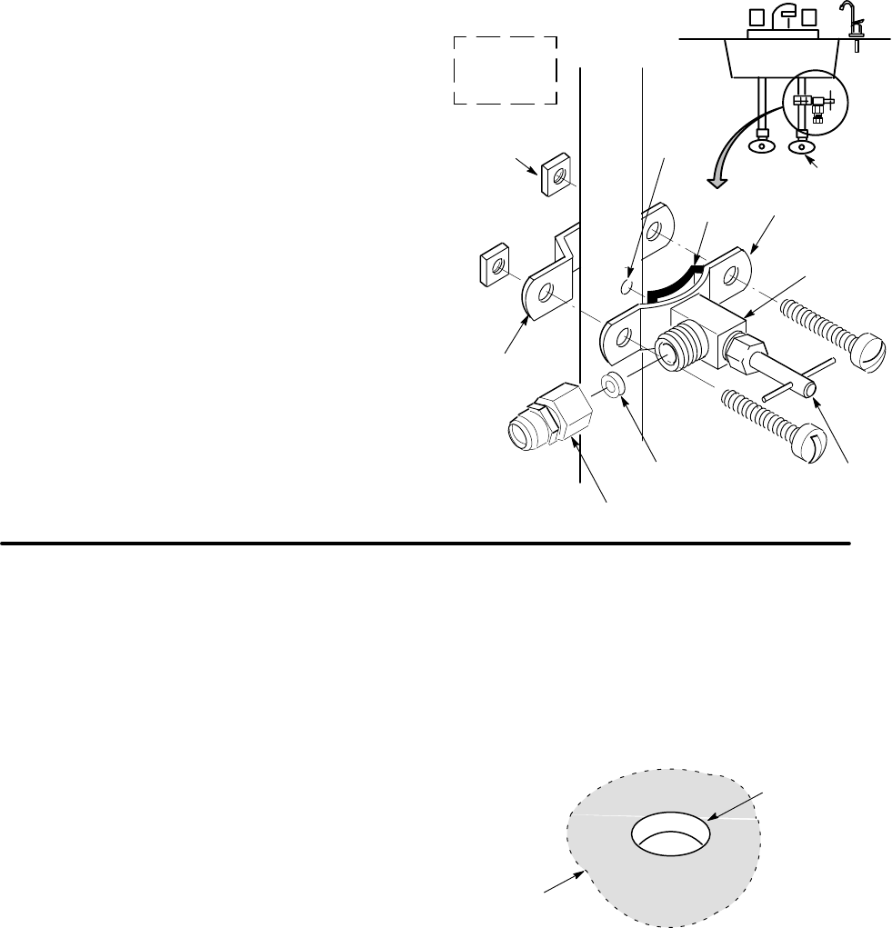
STEP1-WATERSUPPLYSADDLE VALVE
Check and comply with local plumbing codes before
you install a cold water supply fitting. The special self-
tapping (into copper) saddle valve included installs as
follows. Locate the valve on the cold water pipe to the
kitchen sink, as shown in FIG. 1.
Note: This valve has a cutting pin and it will pierce a
hole in copper tubing or plastic pipe. If installing on
iron pipe, you have to drill a 1/8" hole for the piercing
pin (read danger note below).
DANGER (IF DRILLING METAL PIPE): To protect
yourself from serious injury or fatal shock, use a
battery powered hand drill only to make the hole. Do
not use an electric drill.
1. Be sure to turn off water to the pipe and to
drain water from it before drilling.
Note: If the sink faucet is a single lever, mixing type,
also close the shutoff valve on the hot water side.
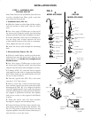
2. Looking at FIG. 2, turn the valve into clamp A and
tighten (may be preassembled). Turn the valve handle
all the way out.
Note: If you need to drill a 1/8" dia. hole, Hold clamp
A up to the pipe and mark the spot to drill. First, read
the danger note above.
3. Place the seal on the inside of clamp A as shown.
Be sure the piercing pin does not stick out beĆ
yond the seal. (If you drilled the hole, turn the piercĆ
ing pin out enough to align with it.)
4. Place clamp A and B around the pipe and secure
in place with 2 screws. Tighten both screws evenly,
but do not overtighten and crush the pipe.
5. Carefully turn the handle all the way inward to
pierce a hole in the copper or plastic pipe.
6. Put a few wraps of Teflon tape on the valve body
threads. Then, with the washer in place, turn the tubĆ
ing adaptor onto the valve and tighten securely.
Note: Be sure the valve packing nut is tightened. Do
not turn on the water supply at this time.
FIG. 2
SINK
handle
washer
adaptor
clamp A
clamp B
nut (2) –
not req’d
with all types of
clamp B
seal
pre–drill
1/8” hole
(iron pipe)
cold
water
valve
Check local
codes for
approval
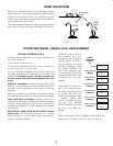
STEP 2 - MAKE HOLE FOR FILTERED
WATER FAUCET
Select 1 of the following places to install the faucet. Be
sure there's room underneath so you can make the
needed connections. If you are installing the deluxe
model, be sure the electronic indicator base will fit flat
against the surface.
-- In an existing sink spray attachment hole.
-- Drill a hole in the sink top.
-- Drill a hole in the countertop, next to the sink.
1. If drilling is needed, make a 3/4'" dia. (minimum)
hole for the standard faucet. The faucet with the elecĆ
tronic indicator base requires a 1-1/8" dia. hole.
CAUTION: To avoid damaging the sink, consult a
qualified plumber or installer for drilling procedures
in porcelain or stainless steel. Special drill bits are
made for this.
2. Place plumbers putty around the drilled hole, to
prevent water leaks around the faucet.
FIG. 3
3/4” dia. (stan-
dard faucet) or
1–1/8” dia. (elec-
tronic base fau-
cet) hole through
sink or counter-
top
plumbers
putty