


Before Using Your Range
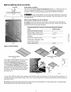
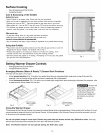
Assembly of Burner Heads & Burner Caps (for Deep Well Cooktop models only)
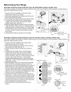
Your range is shipped with the Burner Heads and Burner Caps in the correct locations. Packing material is located between
the Burner Heads and Burner Skirts.
1. Be sure to follow the Installation Instructions before
installing and using your new range.
2. Remove all packing tape from cooktop area. Remove all
Burner Caps and Burner Heads.
3. Discard all packing material located under Burner Heads.
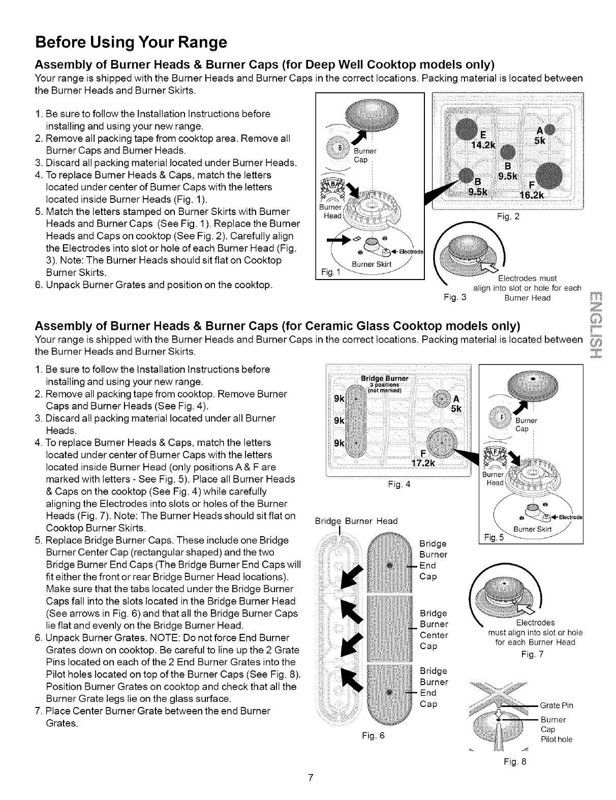
4. To replace Burner Heads & Caps, match the letters
located under center of Burner Caps with the letters
located inside Burner Heads (Fig. 1).
5. Match the letters stamped on Burner Skirts with Burner
Heads and Burner Caps (See Fig. 1). Replace the Burner
Heads and Caps on cooktop (See Fig. 2). Carefully align
the Electrodes into slot or hole of each Burner Head (Fig.
3). Note: The Burner Heads should sit flat on Cooktop
Burner Skirts.
6. Unpack Burner Grates and position on the cooktop.
I
Burner
Cap
3urner ( )_
Head 1_ _::D_._?://
:: Fig. 2
_. BumerS-k_t j
Fig.1
Electrodes must
align into slot or hole for each
Fig. 3 Burner Head
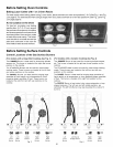
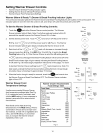
Assembly of Burner Heads & Burner Caps (for Ceramic Glass Cooktop models only) ;_,
Your range is shipped with the Burner Heads and Burner Caps in the correct locations. Packing material is located between
the Burner Heads and Burner Skirts.
1. Be sure to follow the Installation Instructions before
installing and using your new range.
2. Remove all packing tape from cooktop. Remove Burner
Caps and Burner Heads (See Fig. 4).
3. Discard all packing material located under all Burner
Heads.
4. To replace Burner Heads & Caps, match the letters
located under center of Burner Caps with the letters
located inside Burner Head (only positions A & F are
marked with letters - See Fig. 5). Place all Burner Heads
& Caps on the cooktop (See Fig. 4) while carefully
aligning the Electrodes into slots or holes of the Burner
Heads (Fig. 7). Note: The Burner Heads should sit flat on
Cooktop Burner Skirts.
5. Replace Bridge Burner Caps. These include one Bridge
Burner Center Cap (rectangular shaped) and the two
Bridge Burner End Caps (The Bridge Burner End Caps will
fit either the front or rear Bridge Burner Head locations).
Make sure that the tabs located under the Bridge Burner
Caps fall into the slots located in the Bridge Burner Head
(See arrows in Fig. 6) and that all the Bridge Burner Caps
lie flat and evenly on the Bridge Burner Head.
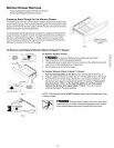
6. Unpack Burner Grates. NOTE: Do not force End Burner
Grates down on cooktop. Be careful to line up the 2 Grate
Pins located on each of the 2 End Burner Grates into the
Pilot holes located on top of the Burner Caps (See Fig. 8).
Position Burner Grates on cooktop and check that all the
Burner Grate legs lie on the glass surface.
7. Place Center Burner Grate between the end Burner
Grates.
8ridg_ Burner
3 p_sltlon_ :
_'S %: (notm_rked)
A
9k!:iiN]
t_ :,3)
............. 7.2k
ii
Fig. 4
Bridg I Burner Head
Bridge
Burner
End
Cap
Bridge
Burner
Center
Cap
Bridge
Burner
End
Cap
Fig. 6
I
Burner
Cap
!:
_. Burner Sk_rirt
R 5_
must align into slot or hole
for each Burner Head
Fig. 7
Fig. 8