


14
4. Now you are ready to connect the copper tubing to the
shut-off valve. Use
1
⁄
4
" (6.35 mm) O.D. (outside diameter)
soft copper tubing to connect the shut-off valve and the
refrigerator.
■ Ensure that you have the proper length needed for the job.
Be sure both ends of the copper tubing are cut square.
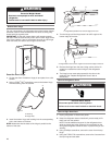
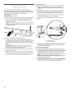
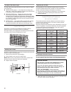
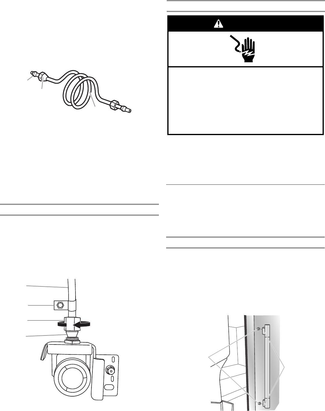
■ Slip compression sleeve and compression nut onto copper
tubing as shown. Insert end of tubing into outlet end squarely
as far as it will go. Screw compression nut onto outlet end
with adjustable wrench. Do not overtighten.
A. Compression sleeve
B. Compression nut
C. Copper tubing
5. Place the free end of the tubing into a container or sink and
turn on main water supply to flush out tubing until water is
clear. Turn off shut-off valve on the water pipe.
NOTE: Always drain the water line before making the final
connection to the inlet of the water valve to avoid possible
water valve malfunction.
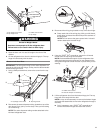
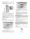
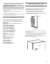
6. Bend the copper tubing to meet the water line inlet which
is located on the back of the refrigerator cabinet as shown.
Leave a coil of copper tubing to allow the refrigerator to be
pulled out of the cabinet or away from the wall for service.
Connect to Refrigerator
Follow the connection instructions specific to your model.
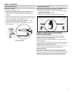
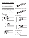
1. Remove plastic cap from water valve inlet port. Attach the
copper tubing to the valve inlet using a compression nut
and sleeve as shown. Tighten the compression nut. Do not
overtighten. Confirm copper tubing is secure by pulling on
copper tubing.
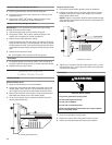
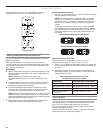
2. Create a service loop with the copper tubing. Avoid kinks
when coiling the copper tubing. Secure copper tubing to
refrigerator cabinet with a “P” clamp.
A
C
B
A. Copper tubing
B. “P” clamp
C. Compression nut
D. Compression sleeve
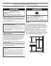
Complete the Installation
1. Plug into a grounded 3 prong outlet.
2. Flush the water system. See “Water and Ice Dispensers”
section.
NOTE: Allow 24 hours to produce the first batch of ice. Discard
the first 3 batches of ice produced. Allow 3 days to completely
fill the ice storage bin.
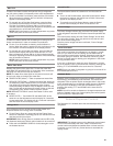
A. Shoulder screws
B. Setscrews inside the handle
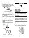
Electrical Shock Hazard
Plug into a grounded 3 prong outlet.
Do not remove ground prong.
Do not use an adapter.
Do not use an extension cord.
Failure to follow these instructions can result in death,
fire, or electrical shock.
WARNING
A
B
C
D
3. Turn on water supply to refrigerator and check for leaks.
Correct any leaks.
Handle Installation and Removal
Parts Included: refrigerator door handles (2), refrigerated
drawer handles (2), freezer drawer handle (1),
1
⁄
8
" hex key, spare
setscrew(s)
NOTE: The freezer drawer handle is shorter than the refrigerator
door handles. Handle style may vary by model.
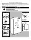
Install Handles
Refrigerator Doors
NOTE: Handle mounting setscrews are preinstalled inside the
handle.
1. Remove the handles from the packaging inside the
refrigerator and place them on a soft surface.
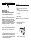
2. Open a refrigerator compartment door. On the closed
door, place a handle onto the shoulder screws so that the
setscrews are facing the adjacent door.
A
B