


7
ENGLISH
ELECTRICAL CONNECTIONS
ELECTRICAL CONNECTION
REQUIREMENTS
This appliance must be installed and grounded on a
branch circuit by a qualied technician in accordance
with the National Electrical code ANSI/NFPA NO. 70 -
latest edition.
All wiring should conform to Local and NEC. This range
requires a single-phase, 3 wire, A.C 120/208V or 120/240V
60Hz electrical system. Use only a 3-conductor or a
4-conductor UL-listed range cord with closed-loop
terminals, open-end spade lugs with upturned ends
or similar termination. DO NOT install the power cord
without a strain relief.
A range cord rated at 40 amps with 120/240 minimum
volt range is required. If a 50 amp range cord is used, it
should be marked for use with 13⁄8” diameter connection
openings. This appliance may be connected by means
of conduit or power cord. If conduit is being used, go to
page 7 for 3 wire conduit connections or page 8 for 4
wire conduit connections.
• New branch-circuit installations (1996 NEC)
for mobile homes, recreational vehicles, and
installations where local codes do not allow
grounding through the neutral wire require
a 4-conductor UL listed range cord or 4 wire
conduit connection.
• Power supply cord and plug should not be
modied. If it will not t the outlet, have a
• Using an extension cord to connect the power is
prohibited. The way to connect the power cord
and plug directly is strongly recommended.
• Electrical ground is required on this appliance.
• You should make sure that the power cord is
not pinched by the range or heavy objects.
- Failure to do so can result in serious burns or
electrical shock.
WARNING
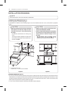
Range rating, watts
rating of power
supply-cord kit,
amperes
Diameter (inches) of Range
connection Opening
120/240 volts
3-wire
120/208 volts
3-wire
Power cord Conduit
8,750 - 16,500
16,501 - 22,500
7,801 - 12,500
12,501 - 18,500
40 or 50A
50
1
3
/
8
”
1
3
/
4
”
1
1
/
8
”
1
3
/
8
”
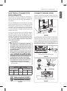
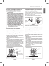
3, 4 - Wire electrical wall Receptacle
4 Wire receptacle (14-50R)
3 Wire receptacle (10-50R)
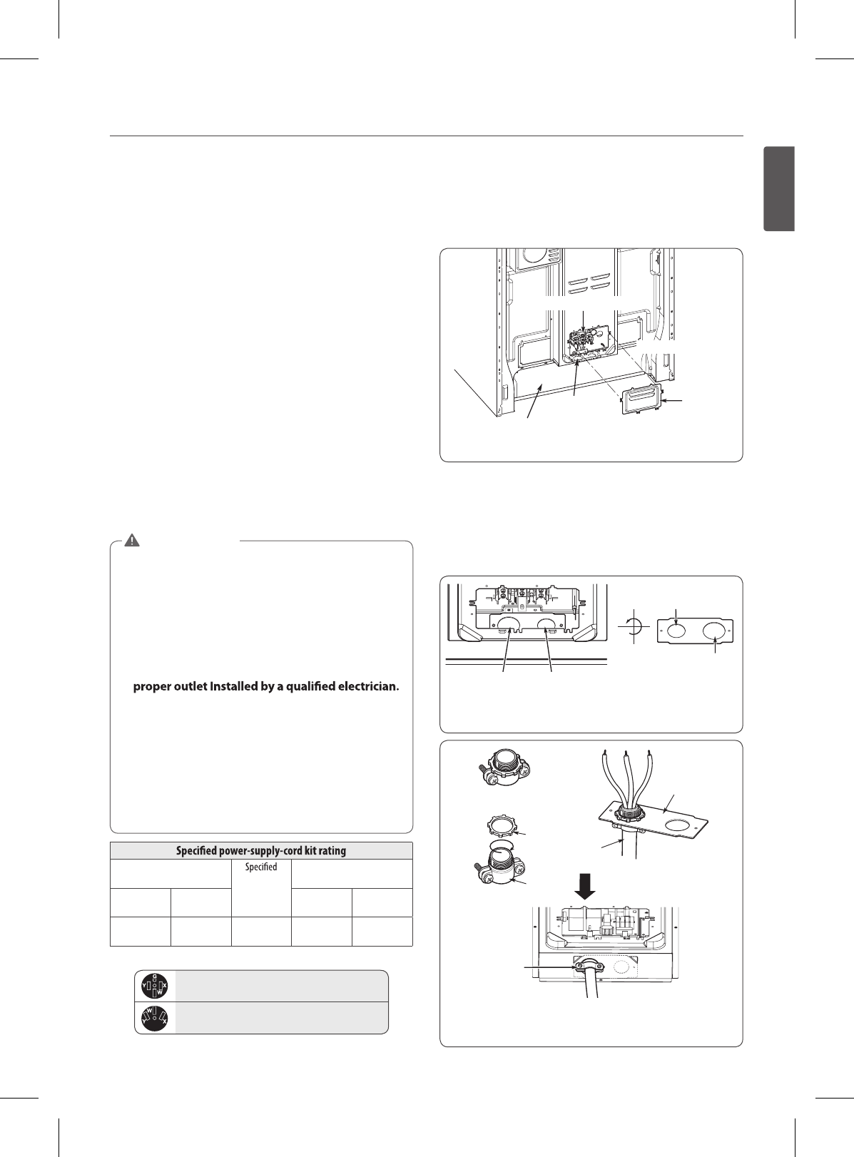
FIgURE 3
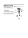
CONNECT RANGE CORD
The Rear Access cover must be removed. Loosen the
three screws with a screwdriver. The terminal block will
then be accessible.
FIgURE 4
Terminal block
Drawer body
Access
cover
Power cord outlet
Cord/Conduit
connection
plate
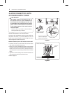
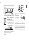
The Cord/Conduit connection plate is used for the
installation of power cord or conduit. For power cord,
install it with the connection plate as INSTALLED. For
conduit, remove the connection plate located below the
rear of the drawer body and use the conduit hole (1
1
/
8
”)
instead of power cord hole (1
3
/
8
” ). (Refer to Figure 5 and 6.)
1
3
/
8
"
(3.5cm)
1
3
/
8
"(Cord) 1
1
/
8
"(Conduit)
1
1
/
8
"
(2.8cm)
Remove the Conduit connection plate
FIgURE 5
FIgURE 6
Strain relief
Conduit
Assemble the
strain relief hole
Reinstall the Cord/Conduit connection plate
Ring
Cord Strain
relief
Conduit
Body
Cord/conduit
connection
plate