


LIGHTOLIER a GENLYTE company.
631 Airport Road, Fall River, MA 02720
(508) 679-8131 FAX (508) 647-4710
© 1995
Read and understand these instructions before installing fixture.
This fixture is intended for installation in accordance with the National Electrical Code and local or Federal
code specifications. To prevent electric shock, turn off electricity at fuse box before proceeding.
Retain these instructions for maintenance reference.
IS:4531
0995Page 1 of 2
NOTE:
This instruction sheet covers both compact fluorescent and incandescent fixtures. Although illustration shows compact fluorescent, the
incandescent version assembles and installs in the same manner.
NOTE:
The Backplate is provided with (3) Auxiliary Mounting Knockout
Holes (4531, 4532, 4551, and 4552 series fixtures) for direct
mounting to wall surfaces. These can be used for added security or
where direct Outlet Box mounting is not available. To remove plug
in Knockout Holes, follow steps 1 through 3 below.
For 4533 series fixtures, (4) Auxiliary Mounting Knockout Holes
are provided for direct mounting to wall surfaces (no plugs to
remove). It is recommended that Auxiliary Mounting Holes be
used on 4532, 4533 and 4552 series fixtures.
The Backplate can be mounted horizontally of vertically. See Fig 1
below for proper orientation for type of Lens Assembly and desired
position.
1. Position blunt ended punch or awl in center of Knockout hole and
firmly hit with hammer to punch plug through. Repeat for remaining
Knockouts (Fig. 1).
Caution: Always wear eye protection (safety goggles) when
removing Auxiliary Mounting Knock-Outs.
2. Position Backplate in desired position over Outlet Box and mark
location of (4) Auxiliary Holes on wall surface.
3. Determine the appropriate mounting hardware required for type of
wall material fixture is being mounted to (i.e. toggle bolts or molly
screws for plaster or gysum board walls, wood screws, etc.)
4. Thread Crossbar Mounting Screws into Crossbar as shown in
Fig. 1.
5. Using appropriate slots in Crossbar, secure Crossbar to Outlet
Box using Outlet Box Screws (provided with Outlet Box).
6. While supporting Backplate make connections: black fixture lead
or fixture without tracer marks to hot (black) supply lead; white
fixture lead or fixture lead with tracer markers to neutral (white)
supply lead. Un-insulated wire is a ground wire and must be
connected to grounding terminals or ground lead inside Outlet Box.
Use Wire Nuts (local hardware item). Push connections back into
Outlet Box.
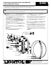
FIG.1
Instructions for Installation of Arco 4531, 4532, 4533,
4551, and 4552 Series Fixtures.
Wire Nut
Outlet Box
Crossbar
Outlet Box Screws
Ground Wire
Backplate
Gasket
Mounting Hole
Safety Cable
Battery Nut
Loop
Mounting Screw
Lens Assembly
Crossbar Mounting
Screws
Auxiliary Mounting
Knock-out
Position this edge
of Backplate up
for mounting of this
Lens Assembly as shown
Position this edge
of Backplate
up for horizontal
mounting of this
Lens Assembly