


17
CDVX Series Direct Vent Gas Fireplace
20012253
needs to have an immediate rise before going hori-
zontal. NOTE: Be careful not to distort the outer flex
as this will affect the performance of the fireplace.
6. Secure the collar to the firestop by bending the tab
out on the firestop and running a screw through the
tab and collar.
7. From outside the house, slide the termination onto
the collars sticking through the firestop.
8. Secure the termination to the house with the four (4)
screws provided. Be sure to seal around the termi-
nation and house cladding.
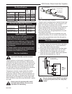
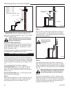
Vertical Sidewall Applications
Since it is very important that the vent-
ing system maintain its balance between
the combustion air intake and the flue
gas exhaust, certain limitations as to vent
configurations apply and must be strictly
adhered to.
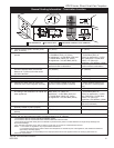
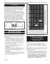
The Vent Graph shows the relationship between vertical
and horizontal side wall venting and will help to deter-
mine the various dimensions allowable.
Minimum clearance between vent pipes
and combustible materials is 1” (25 mm)
on top, bottom and sides unless otherwise
noted.
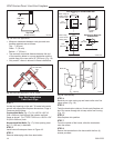
When vent termination exits through foundations less
than 20” below siding outcrop, the vent pipe must
flush up with the siding. It is always best to locate the
fireplace in such a way that minimizes the number of
offsets and horizontal vent length.
The horizontal vent run refers to the total length of vent
pipe from the flue collar of the fireplace to the face of
the outer wall.
Horizontal plane means no vertical rise exists on this
portion of the vent assembly.
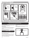
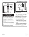
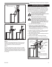
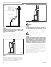
• The maximum horizontal vent run is 20 ft. (6.1 m)
when the vertical vent rise is 7¹⁄₂ ft. (2.3 m). (Fig. 26)
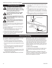
• The maximum number of 90° elbows per side wall
installation is three (3).
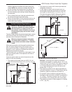
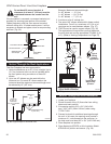
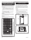
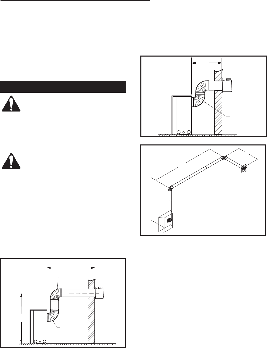
• If a 90° elbow is used in the horizontal vent run
(level height maintained) the maximum horizontal
vent length is reduced by 36” (914 mm). (Fig. 27)
This does not apply if the 90° elbows are used to
increase or redirect a vertical rise. (Fig. 28)
V584-201
Horizontal Run
2/99 djt
10 ft.
(3048 mm)
7 ft. 6 in.
(2286 mm)
7 ft.
(2134 mm)
CFM147
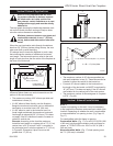
Fig. 28 Maximum vent run with elbows.
90° Elbow = 3 ft.
A + B = 17 ft. (Max.)
Maximum
3' (914mm)
CFM142
Venting
2/2/01 sta
CFM142
Fig. 27 Maximum horizontal vent run.
7TCDV90
Example: According to the chart the maximum
horizontal vent length in a system with a 7.5’ (2.3 m)
vertical rise is 20’ (6 m) and if a 90° elbow is required
in the horizontal vent it must be reduced to 17’ (5.2
m). In Figure 28 Dimension A plus B must not be
greater than 17’ (5.2 m).
• The maximum number of 45° elbows permitted per
side wall installation is two (2). These elbows can be
installed in either the vertical or horizontal run.
• For each 45° elbow installed in the horizontal run,
the length of the horizontal run MUST be reduced by
18” (45 cm). This does not apply if the 45° elbows
are installed on the vertical part of the vent system.
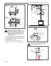
• The maximum number of elbow degrees in a system
is 270°. (Fig. 29)
CFM141
2/2/01 sta
Maximum
20 ft. (6.1m)
7.5'
(2.3m)
Vertical Dimension
7¹⁄₂’ Minimum When
Horizontal Run is
20’
CFM141
Fig. 26 Maximum number of 90° elbows is three (3).
7TCDV90
7TDV90