


GSI 200 TIMER/BACK COVER REPLACEMENT
Installation Instructions
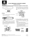
REPLACING THE TIMER CIRCUIT BOARD REQUIRES REPLACEMENT OF THE BACK PANEL
Timer Housing Back Cover
Timer Circuit Board
All Models
1. Install two (2) fresh AA batteries in timer housing
noting proper polarity (+/-).
2.
Verify timer circuit board is in the correct
position. Snapping the control board under all
four legs will correctly position the control board.
The circuit board is incorrectly positioned if both
lights (red and green) flash at the same time when
the rear cover is installed.
3. Verify the small key slots are on the right side
when viewed from the front of the timer housing.
Align sachet holder mounting plate holes with
pins in the timer cover housing and snap into
place.
4. Use four pan-head screws to secure the back
cover/sachet mounting plate to the timer housing.
5. Attach sachet holder to mounting plate. Final
assembly will be with sachet holder opening
facing up.
a. Rotate sachet holder 90 clockwise.
b. Refer to table to determine if upper or lower
keyhole slots are used. Place left side pin in
the sachet mounting plate keyhole.
c. Rotate sachet holder 90 counterclockwise and
place right side pin in keyhole slot.
d. Push sachet holder down into keyhole slots to
secure.
Manitowoc Ice, Inc.
2110 South 26th Street, P.O. Box 1720, Manitowoc, WI 54221-1720 USA 8014383
Telephone 920-682-0161, Fax - Sales: 920-683-7589, Service/Parts: 920-683-7585, Other: 920-683-7879 Sheet 1 of 2
Web Site - www.manitowocice.com 03/12/03
RESET BUTTON
FINAL POSITION IS
WITH OPENING
FACING UP
ROTATE 90 TO
ATTACH LEFT SIDE,
THEN ROTATE TO
FINAL POSITION TO
ATTACH RIGHT SIDE
Attach Sachet
Mounting Plate to Back
Cover Pins
Upper Keyhole Slot
Small Keyhole Slots on
right side when viewed
from front
Lower Keyhole Slot
PLACE TIMER BOARD ON
THE FOUR SUPPORTS
SNAP THE CONTROL BOARD UNDER
ALL FOUR LEGS TO SECURE
POSITIVE
TERMINALS