


33 16022783 Rev. 0 ©2004 Maytag Appliances Company
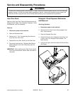
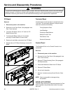
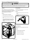
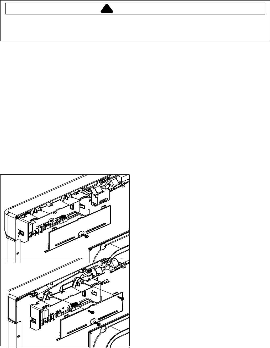
PC Board
Removal
1. Disconnect power to the machine.
2. Remove the Inner Door Panel. (See paragraph Inner
Door Panel removal).
3. To access PC Board, remove 1/4" screw on PC
Board Housing Cover.
4. To remove PC Board, loosen (2) 1/4" screws
securing PC Board Base to Control Panel.
5. Remove pin and ribbon connectors from PC Board.
6. Depress tabs on PC Board Housing to remove PC
Board.
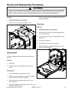
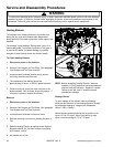
Technical Sheet
The Dishwasher Technical Sheet is located behind the
Toe Panel. The Schematic Diagram is unique to each
model and contains the following:
Timing Sequence Chart
Load Readings
Component Specifications
Manual Function Test
Field Service Test
Electrical Schematic
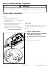
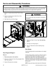
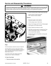
Control Panel
The Membrane/Facia on the Control Console is not
replaceable.
Removal
1. Disconnect power to the machine.
2. Remove the Inner Door Panel. (See paragraph Inner
Door Panel removal).
3. Remove PC Board Housing Cover. (See paragraph
PC Board removal).
4. Disconnect Membrane Switch from PC Board.
5. Remove PC Board Base.
6. Lift out Latch Assembly.
7. Remove 4 screws securing Control Panel to Outer
Door.
NOTE: Facia is susceptible to damage during
reinstallation.
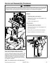
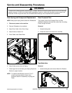
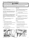
DOOR LATCH STRIKE
The Door Latch serves as a mechanical actuator for Door
Switch operation and provides door tension for proper
door seal.
Service and Disassembly Procedures
! WARNING
To avoid risk of electrical shock, personal injury, or death, disconnect electrical power source to unit and discharge
capacitor through a 10,000 ohm resistor before attempting to service, unless test procedures require power to be
connected. Ensure all ground wires are connected before certifying unit as repaired and/or operational.