Page 1
MODEL 768CHNT
DECORATIVE
VENTILATION FAN WITH LIGHT
READ AND SAVE THESE INSTRUCTIONS
WARNING
TO REDUCE THE RISK OF FIRE, ELECTRIC SHOCK, OR
INJURY TO PERSONS, OBSERVE THE FOLLOWING:
1. Use this unit only in the manner intended by the manufac-
turer. If you have questions, contact the manufacturer at
the address or telephone number listed in the warranty.
2. Before servicing or cleaning unit, switch power off at
service panel and lock the service disconnecting means
to prevent power from being switched on accidentally.
When the service disconnecting means cannot be locked,
securely fasten a prominent warning device, such as a
tag, to the service panel.
3. Installation work and electrical wiring must be done by
a qualified person(s) in accordance with all applicable
codes and standards, including fire-rated construction
codes and standards.
4. Sufficient air is needed for proper combustion and
exhausting of gases through the flue (chimney) of fuel
burning equipment to prevent backdrafting. Follow the
heating equipment manufacturer’s guideline and safety
standards such as those published by the National Fire
Protection Association (NFPA), and the American Society
for Heating, Refrigeration and Air Conditioning Engineers
(ASHRAE), and the local code authorities.
5. When cutting or drilling into wall or ceiling, do not dam-
age electrical wiring and other hidden utilities.
6. Ducted fans must always be vented to the outdoors.
7. NEVER place a switch where it can be reached from a
tub or shower.
8. This
unit must be grounded.
9.
This unit is U.L. listed. Type I.C. inherently protected.
CAUTION
!
1. For general ventilating use only. Do not use to exhaust
hazardous or explosive materials and vapors.
2. This product is designed for installation in FLAT CEILINGS
ONLY. Do not mount this product in a wall.
3. The light fixture assembly must be mounted to the fan
housing assembly included with this product. Do not
mount the light fixture assembly to a wiring outlet box.
4. To avoid motor bearing damage and noisy and/or unbal-
anced impellers, keep drywall spray, construction dust,
etc. off power unit.
5. Please read specification label on product for further
information and requirements.
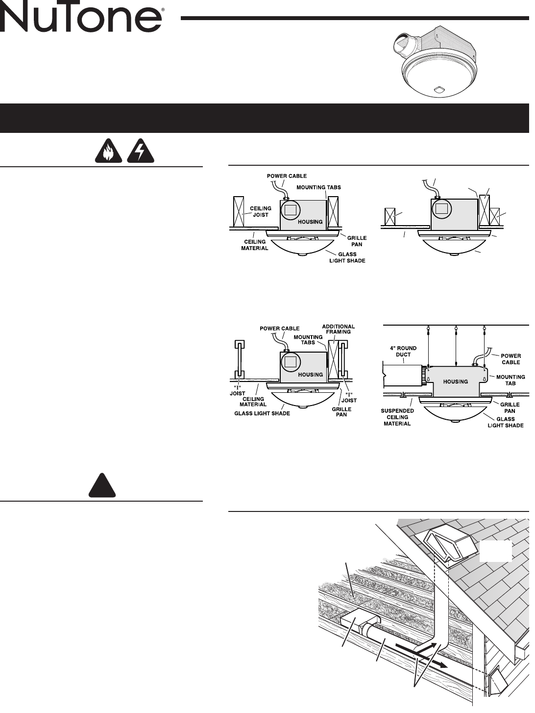
TYPICAL INSTALLATIONS
HOUSING MOUNTED
DIRECTLY TO JOIST
2x6 (or larger)
Discharge parallel to joists.
HOUSING
2 x 4
CEILING
JOIST or
TRUSS
MOUNTING
TABS
POWER CABLE
ADDITIONAL
FRAMING
2 x 4
TRUSS
CEILING
MATERIAL
GRILLE
PAN
GLASS
LIGHT SHADE
HOUSING MOUNTED
TO 2x4 TRUSS
Requires additional framing
for mounting tabs.
Discharge parallel to joists.
HOUSING MOUNTED
TO “I” JOIST
Requires additional framing
for mounting tabs.
Discharge parallel to joists.
Installer:
Leave this manual with the
homeowner.
Homeowner:
Use and Care information on page 4.
*
Additional framing must be a 2x6 (minimum height), at least 9-inches long.
*
*
SUSPENDED CEILINGS
Housing hung with wires -
3-point mount.
PLAN THE INSTALLATION
The unit will operate
most quietly and
efficiently when
located where the
shortest possible
duct run and
minimum number
of elbows will be
needed.
Use a roof cap or
wall cap that has a
built-in damper to
reduce backdrafts.
Plan to supply the
unit with proper
line voltage and
appropriate power
cable.
ROOF
CAP
*
4-IN. ROUND
ELBOW(S)
*
4-IN.
ROUND
DUCT
*
WALL CAP
*
*
Purchase
separately
INSULATION
(Can be placed
around and over
fan housing.)
FAN
HOUSING


