


Orecon
SCIENTIFIC
Wireless
Indoor/Outdoor
Thermometer
with Dual
Alarm
Clock
Model:
RAR188A
User Manual
Thank
you
for
selecting the
Oregon ScientificrM Wireless
Indoor /
Outdoor Themometer
with Dual
Alarm Clock
(RAR188A).
This
device
bundles
precise
time-keeping,
alarm,
and temperature monitoring
fea-
tures into
a single tool
you
can
use from the convenience
of
your
home.
ln this
box,
you
will find:
.
l\y'ain unit
.
Remote sensor
(THN122N)
Keep this manual handy
as
you
use
your
new
product.
lt
contains
practical
step-by-step
instructions,
as well as techn
cal speciflcations
and
warnings
you
should know
abo!t.
9.
10
4.
5.
6.
1
2
3
4
Clock Area: Tlme
display with seconds
or days
of the week
Calendar
/ Alarm Area: Date
display and
duat alarm display
Temperature Trend
Indicator: shows if
temperature
is rising,
steady, or fal ing
Outdoor Battery
Indicator:
Shows when remote
sensor
battery
is low on
power
Indoor Battery
Indicator:
Shows when
main unit battery
is low
on
power
Alarm 1 Indicator:
Displays
when alarm 1
is set and
goes
off
Alarm 2 Indicator:
Displays
when alarm 2 is
set and
goes
off
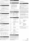
'1.
LED Status indicator
Wall mount hole
RESET
Channel
number
(1
- 3)
Battery compartment
(Battery
compartment
cover not shown)
The main unit is
shipped with a THN122N
Thermo
Sensor that
col-
lects temperature
data
and can be connected
to 3 THN122N remote
sensors to collect
additional temperature
data. Additional
sensors
sold separately.
To
set up
your
remote
sensor:
1.
Open the remote
sensor batterycompartmentwith
a
small Phillips
screwdnver.
2. lnsert the
batteries, matching
the
polarjty
(+
and -) as shown
in
the battery compartment.
F;IFI
t,*t&
.Il_q:IF:
Standard Alkaline
batteries contain
signifcant amounts
of
watet
Because ofthis
they will freeze in low temperatures
of approxi-
mately 10'F
(-12'C).
Disposable Lithium
batteries havea
much lower
threshold
for temperature
with an estimated
freezing range
of
below -40"F
C40'C).
The
Liquid Crystal Display
in outdoor
thermom-
eters will remain
operational to
-20'F
(-28'C)
with adequate
power
Wireless ranges
can
be
impacted
by a variety
of factors
such as ex-
tremely cold temperatufes.
Extreme
cold may temporarily
reduce the
effective range
between the sensor
and the
base station. lf the
unit's
performance
fails due to
low temperature, the
unit will resume
proper
functioning
as the temperature
rises to within
the normal
temperature
range (i.e
no
permanent
damage will
occur to the unit
due to low tem-
peratures).
3. Set the
channel switch to
any channel. The
switch is located in
the
battery compartment.
1.
2_
3.
4.
5.
LCD Display
CHANNEL: Press
to switch remote
sensor
MEM: Press
to view current
or saved max /
min temoerature
((.)):
Press to view
dual alarm
settings
MODE: Press
to change display
/ settings
1. Wall
mount hole
2.
A
: Press to increase
settings
3.
V:
Press
to decrease settings
4. Battery compartment
5.
Table
stand
6. AL ON / OFF : Press
to toggle alarm
settings
7.
"C
/
"F
switch
Reception Signal:
Displays when
sensor is
successfully found
for data transmission
Sensor Temperature
Area:
Readings, trend
line, and sensor
re-
ception status and
channel number
Indoor Temperature
Area: Readings,
and indoor symbol
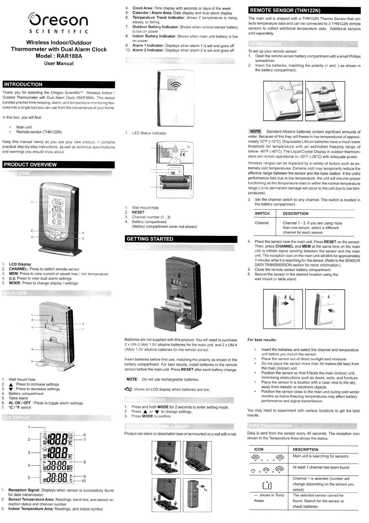
Batteries are not
supplied with
this
product.
You
will
need
to
purchase
2 x UIV-3
(M)
1.5V
alkaline batteries
for the main
unit, and 2 x
Ul\y'-4
(AAA)
1.5V
alkaline batteries for
the remote sensof.
Insert
batteries before first
use, matching
the
polarity
as shown in the
battery compartment.
For best results,
install
batteries in the remote
sensor before
the main unit. Press
RESET
after each battery
change.
NOTE Do
not use rechargeable
batteries.
N
shows
on LCD displaywhen
batteries
are low.
'1.
Press
and hold MODE
for 2 seconds
to enter
setting mode.
2. Pfess
or
V
to change
settings.
3. Press MODE to
confirm.
.,,::
..,,,ir,r:jrniL{},rf.j.f{
Product€n stand
on detachable
base or be mounted
on a wall with a nail.
ffi@
Place
the sensor nearthe
main unit. Press
RESET on
the sensoL
Then,
press
CHANNEL
and MEM at the
same time on
the main
unit to initiate
signal sending between
the sensor and
the main
unit. The reception
icon on the main
unit will blinkforapproximately
3 minutes while it is
searching for the sensol
(Refer
to the
SENSOR
DATATRANSI\,4lSSlON
section for more information.)
Close the remote
sensor battery
compartment.
Secure
the sensor in
the desired location
usinq the
wall mount
or table stand.
ffiH
For best results:
.
Insert the
batteries and select
the channel and
temperature
unit before
you
mount the sensor.
.
Place the
sensor out of direct
sunlight and moisture.
.
Do not
place
the sensor more
than 30 meters(98
feet) from
the main
(indoor)
unit.
.
Position the
sensor so that it faces
the main
(indoor)
unit,
minimizing
obstructjons
such as doors, walls,
and furniture.
.
Place
the sensor
in a location with
a clear view to
the sky,
away from
metallic or electronic
objects.
.
Position
the sensor close
to the main unit
during cold winter
months
as below-freezing
temperatures
may affect
battery
performance
and signal transmission.
You may need
to experiment
with various locations
to
get
the best
resutts.
Data is sent
from the
sensor every 40 seconds.
The reception
icon
shown in the
Temperature
Area shows the status.
:lltli:lr]+:ffi
Channel 1 - 3. lf
you
are using more
than one sensor,
select a different
channel
for each sensor.
l\,4ain
unit is searching for
sensors.
At least
1 channel has
been found
Channel 1
is selected
(number
will
change depending
on the sensor
you
The selected sensor
cannot be
found.
Search for the
sensor or
check batteries.
WW