These quality engineered, high-flow filters in 304 Stainless
Steel are widely used and recommended for “Central
Filtration” systems such as required for apartment buildings,
schools, clubs, camps, institutions, farms, restaurants and
cafeterias where outside building installations require flow
rates from 28 - 125 gpm (1,580 - 7,500 gph), when installed
with PENTEK dirt/rust cartridges (Models S1 or P25) for cold
water installations up to 100° F (38° C).
When used with PENTEK taste/odor Model C1 cartridges,
flow rates will range from 12 - 60 gpm (720 - 3,600 gph).
All 304 Stainless Steel filters are shipped without
cartridges installed, featuring a single clamp for fast and
easy removal of the cover.
The internal center rod features a tightening hand knob to
facilitate fast cartridge change-over and sealing. Rated flow
capacities are based on sediment removal with
25-Micron Rated filter cartridges.
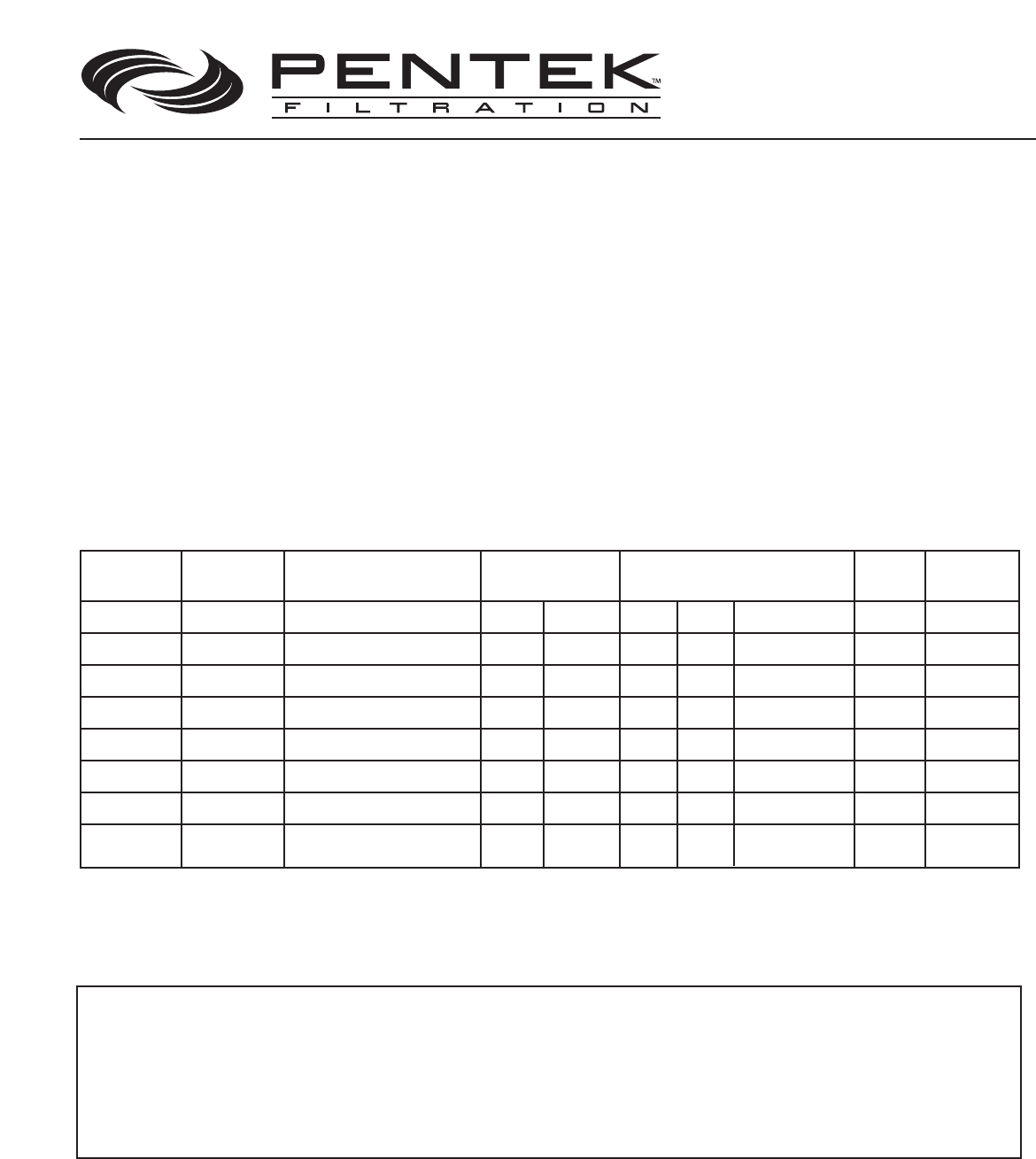
* Above Rated Capacity based on sediment removal with a 25-Micron filter cartridge and 1 psig initial clean pressure drop. For taste/odor removal, rated flow capaci-
ties based on effective contact time are: ST-BC-4, 12gpm; ST-BC-5, 15 gpm; ST-BC-8, 24 gpm; ST-BC-10, 30 gpm; ST-BC-12, 36 gpm; ST-BC-15, 45 gpm; ST-BC-16, 48 gpm;
ST-BC-20, 60 gpm.
** Number of cartridges refers to the number of 9
3
/4
” or 10” cartridges which are configured around the housing times the number of cartridges that may be stacked.
Example: 4X2 means that 9
3
/4
” cartriges are configured four around and two high. Standard housing gasket is Buna-N.
Installation and Operating Instructions
Pentek Models ST-BC-4, ST-BC-5, ST-BC-8, ST-BC-10, ST-BC-12, ST-BC-15, ST-BC-16, ST-BC-20
General
Specifications
IMPORTANT NOTICE — Must Be Read Before Installation
ST-BC-4
ST-BC-5
ST-BC-8
ST-BC-10
ST-BC-12
ST-BC-15
ST-BC-16
ST-BC-20
28 gpm
35 gpm
56 gpm
70 gpm
84 gpm
103 gpm
110 gpm
125 gpm
125 psig - 300° F
125 psig - 300° F
125 psig - 300° F
125 psig - 300° F
125 psig - 300° F
125 psig - 300° F
125 psig - 300° F
125 psig - 300° F
20
20
30
30
40
40
50
50
10"
10"
10"
10"
10"
10"
10"
10"
4X1
5X1
4X2
5X2
4X3
5X3
4X4
5X4
1
1
/2"
1
1
/2"
2"
2"
2"
2"
2"
2"
3"
2
1
/2"
3"
2
1
/2"
3"
2
1
/2"
3"
2
1
/2"
9
3
/4" or 10"
9
3
/4" or 10"
9
3
/4" or 10"
9
3
/4" or 10"
9
3
/4" or 10"
9
3
/4" or 10"
9
3
/4" or 10"
9
3
/4" or 10"
19
1
/4"
19
1
/4"
29"
29"
39
3
/4"
39
3
/4"
49
3
/4"
49
3
/4"
Model
Pipe Size
(NPT)
Shipping
Weight
(Lbs)
Rated
Capacity*
Dimensions
Cartridges
(Maximum)
Height
No.**
OA Dia.
Dia.
Length
Maximun
0perating Pressure
WARNING: The housing MUST BE protected against freezing. Failure to do so may result in cracking of the housing and leakage.
WARNING: If pressure may exceed 125 psi at anytime, a pressure regulator MUST BE used.
WARNING: After opening to install cartridges, make sure to replace cover according to instructions, or it will leak under pressure.
WARNING: DO NOT use air to test housing for leaks.
WARNING: DO NOT use housing for air filtration.
The filter should be mounted in an elevated position permitting
easy draining. The drain plugs located on the filter wall should
be removed, and piping with drain valves installed as in Fig. 1 or 3.
Identify inlet and outlet connections (inlet is always higher
than the outlet).
TAKE CARE NOT TO HOOK THE FILTER UP BACK-
WARDS
. Place filter as shown and connect piping, being sure
to install a shut-off valve on each side of the filter.
NOTE:
When filter is installed next to the water meter or pressure
tank, the main shut-off valve serves as pressure-side (filter
inlet) shut-off.
CONNECTING THE FILTER