


R -8580
DESCRIPTION AND FUNCTION OF COMPONENTS
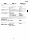
THERMISTOR
The thermistor is a negative temperature coefficient
type. The temperature in the oven cavity is detected
through the resistance of the thermistor, and then the
CPU unit causes the heater relay to operate, thus the
current to the convection heater is turned ON/OFF.
OVEN THERMAL CUT-OUT
The oven thermal cut-out located on the bottom side
of the thermal protection plate is designed to prevent
damage to the convection heater unit if an overheated
condition develops in the tube due to cooling fan fail-
ure, obstructed air ducts, dirty or blocked air intake, etc.
Under normal operation, the oven thermal cut-out re-
mains closed. However, when abnormally high tem-
peratures are reached within the heater unit, the oven
thermal cut-out will open, causing the oven to shut
down.
When the oven has cooled temperature, the oven
thermal cut-out closes.
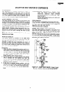
MONITOR SWITCH
The monitor switch is mounted on the upper latch
hook. It is activated (the contacts opened) by the up-
per latch head when the door is closed. The switch is
intended to render the oven inoperative by means of
blowning the fuse when the contacts of the common
and normal open contacts of upper latch switch fail to
open when the door is opened.
Functions:
1.
2.
3.
When the door is opened, the monitor switch con-
tacts close (to the ON condition) due to their being
normally closed. At this time the the common and
normal open contacts of upper latch switch are in
the OFF condition (contacts open) due to their
being normally open contacts switch.
As the door goes to a closed position, the monitor
switch contacts are first opened and then the
common and normal open contacts of upper latch
switch close. (On opening the door, each of these
switches operate inversely.)
If the door is opened during cooking, and the
common and normal open contacts of upper latch
switch fail to open, the monitor fuse blows simul-
taneously with closing of the monitor switch con-
tacts.
CAUTION:BEFORE REPLACING A BLOWN FUSE
TEST THE UPPER LATCH SWITCH AND
MONITOR
SWITCH
FOR
PROPER
OPERATION.(REFER TO CHAPTER “TEST
PROCEDURE”).
AFTER REPLACING FUSE ALSO REPLACE
MONITOR SWITCH.
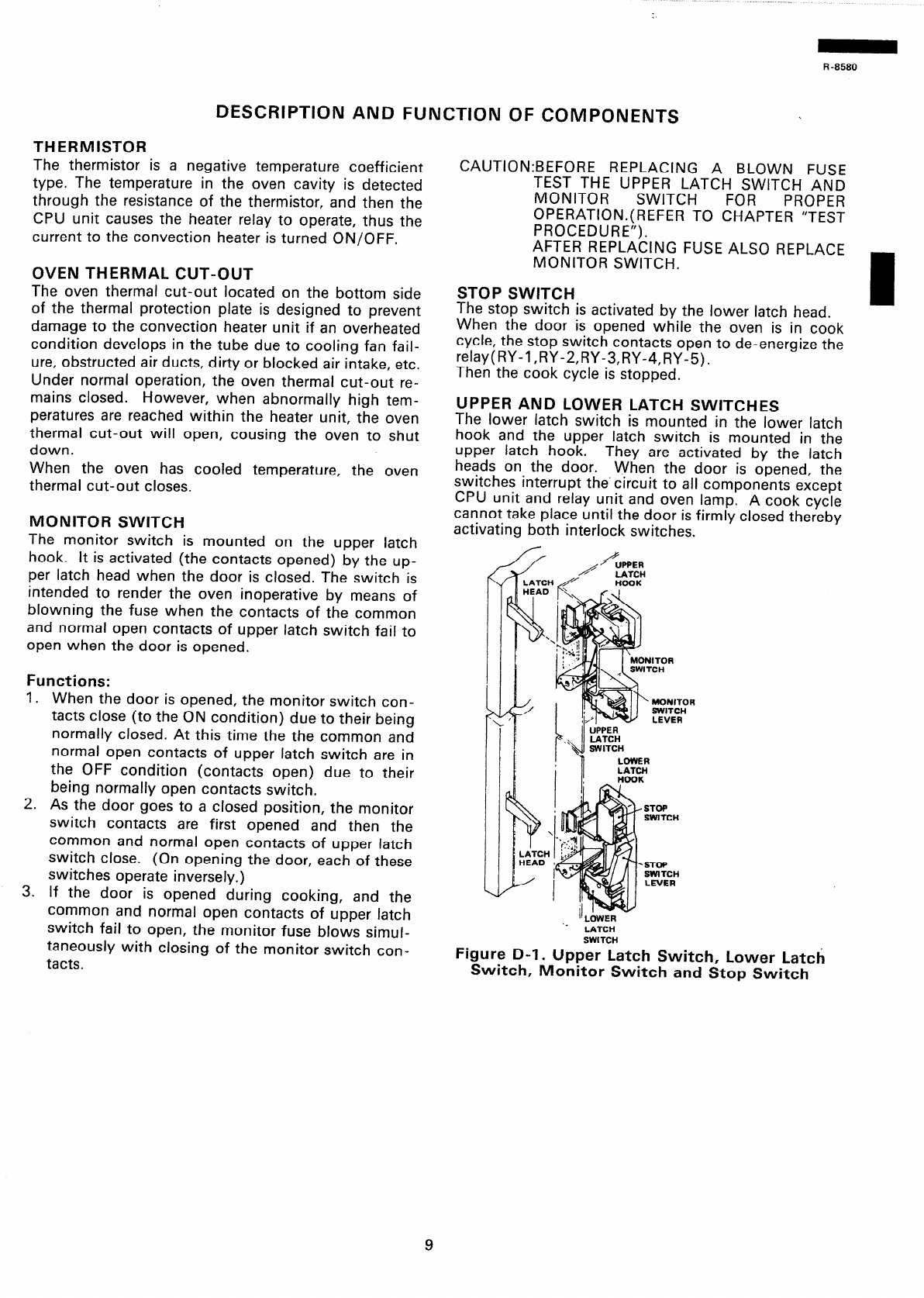
STOP SWITCH
The stop switch is activated by the lower latch head.
When the door is opened while the oven is in cook
cycle, the stop switch contacts open to de-energize the
relay(RY-l,RY-2,RY-3,RY-4,RY-5).
Then the cook cycle is stopped.
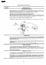
UPPER AND LOWER LATCH SWITCHES
The lower latch switch is mounted in the lower latch
hook and the upper latch switch is mounted in the
upper latch hook.
heads on the door.
They are activated by the latch
When the door is opened, the
switches interrupt the’crrcuit to all components except
CPU unit and relay unit and oven lamp. A cook cycle
cannot take place until the door is firmly closed thereby
activating both interlock switches.
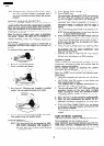
P
A
’ UPPER
LATCH
HOOK
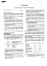
Figure D-l. Upper Latch Switch, Lower Latch
Switch, Monitor Switch and Stop Switch