


R-8580
TOUCH CONTROL PANEL ASSEMBLY
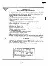
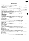
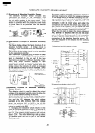
OUTLINE OF TOUCH CONTROL PANEL
The touch control section consists of the following
units as shown in the touch control panel circuit.
(1) Relay Unit
(2) Key Unit
(3) Control Unit
The principal functions of these units and the signals
communicated among them are explained below.
(RD911 A4U)
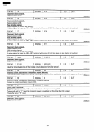
Relay Unit
Relay unit consists of six relays (RYI -RY6), power
source circuit and buzzer circuit.
(RD914BlU)
Key Unit
The key unit is composed of a matrix, signals generated
in the LSI are sent to the key unit through E7,E8,
El 1 -El 3and El 5-E17.
When a key pad is touched, a signal is completed
through the key unit and passed back to the LSI
through AN4-AN7 to perform the function that was
requested.
(RD913Al U)
Control Unit
Control unit consists of LSI, power source circuit,
synchronizing signal circuit, ACL circuit, buzzer circuit,
temperature measurement circuit, absolute humidity
sensor circuit and indicator circuit.
(RD915Bl U)
LSI
This LSI controls the temperature measurement
signal, AH sensor signal, key strobe signal, relay
driving signal for oven function and indicator sig-
nal.
(RD916Al U)
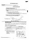
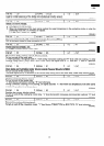
Power Source Circuit
This circuit generates voltages necessary in the
control unit.
Symbol Voltage Application
VC -5v
LSI (ICI ), ACL circuit and tem-
perature measurement circuit
it
-16V
Buzzzer circuit and IC2
+0.5v
IC2
VP
-34v
Fluorescent display tube : Grid
and anode voltage
VFI
-25V
Filament of fluorescent display
tube
VF2
-28V
VFI - VF2 voltage
(RD917Al U)
3)
Synchronizing Signal Circuit
The power source synchronizing signal is available
in order to compose a basic standard time in the
clock circuit.
It accompanies a very small error because it works
on commercial frequency.
4)
ACL Circuit
A circuit to generate a signal which resets the LSI
to the initial state when power is supplied.
5)
Buzzer Circuit
The buzzer is responsive to signals from the LSI
to emit noticing sounds (key touch sound and
completion sound).
6)
(RD91 AA1 U)
Temperature
Measurement Circuit: Oven
temp.
The temperature in the oven cavity is sensed by the
thermistor.
The variation of resistance according to sensed
temperature is detected by the temperature meas-
urement circuit and the result applied to LSI.
The result of detecting is given to LSI controlling
the relay and display.
7)
Absolute Humidity Sensor Circuit
The circuit detects absolute humidity of a food
which is under cooking, to allow its automatic
cooking.
8)
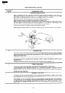
Door Sensing Switch
A switch to “tell” the LSI if the door is open or
closed.
9)
Relay Circuit
To drive the magnetron, heating element, fan mo-
tor, convection motor,damper motor, turntable
(RD918Al U)
(RD919Al U)
(RD91 FBI U)
(RD91 GA1 U)
(RD91 BAZU)
motor and light the oven lamp.
(RD91 CBI U)
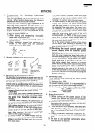
10) Indicator Circuit
Indicator element is a Fluorescent Display.
Basically, a Fluorescent Display is triode having a
cathode, a grid and an anode. Usually, the cathode
of a Fluorescent Display is directly heated and the
filament serves as cathode.
The Fluorescent Display 7-digits, 15-segments are
used for displaying figures.
(RD91 DA1 U)
22