


R-8580
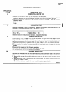
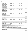
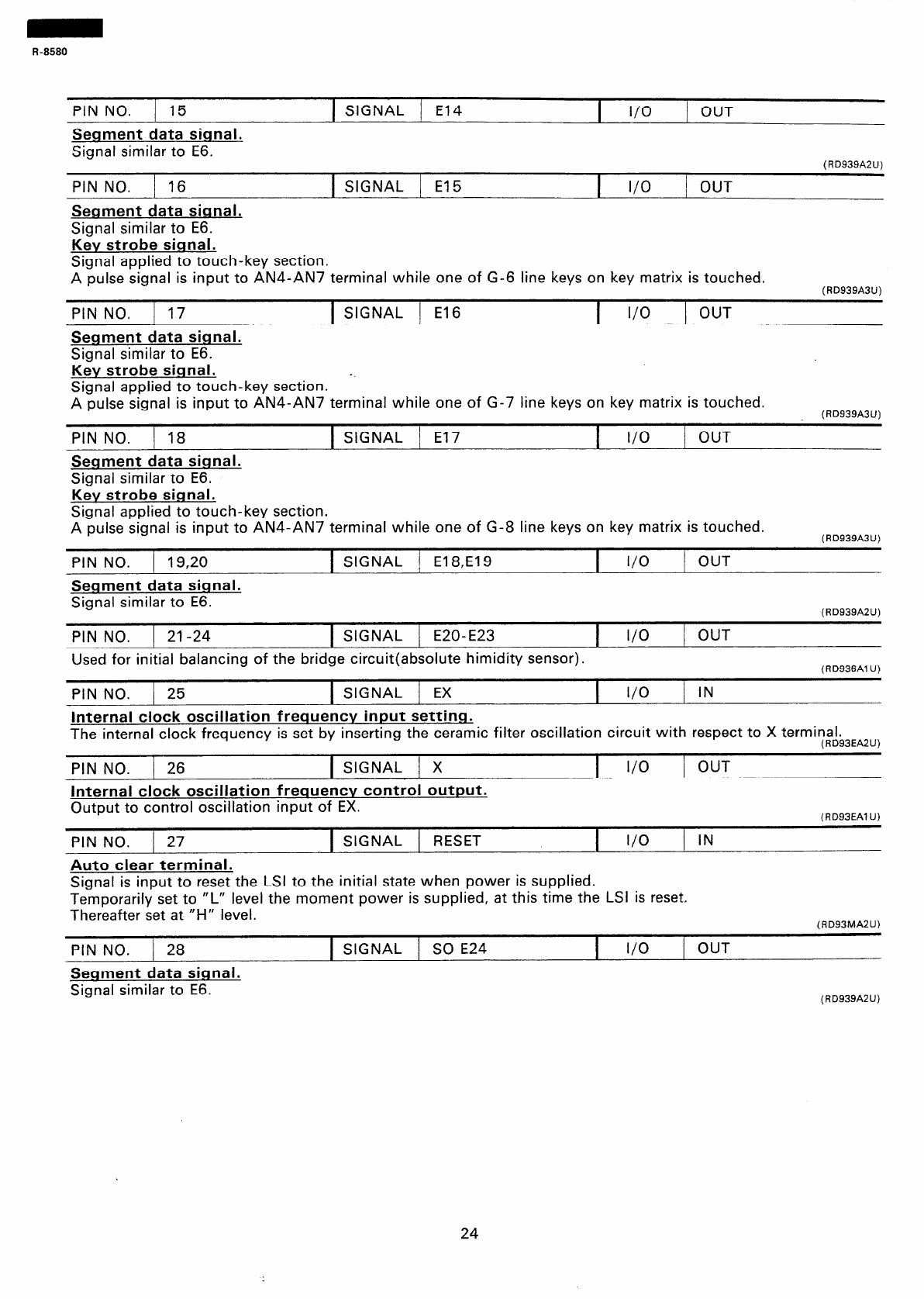
PIN NO. 15
1 SIGNAL / El4
I
I/O
j OUT
Segment data signal.
Signal similar to E6.
PIN NO. / 16
1 SIGNAL j El5
I
I/O
1 OUT
Seqment data siqnal.
Signal similar to E6.
Kev strobe siqnal.
Signal applied to touch-key section.
A pulse signal is input to AN4-AN7 terminal while one of G-6 line keys on key matrix is touched.
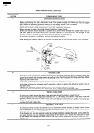
(RD939A2U)
(RD939A3U)
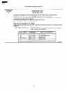
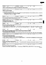
PINNO. I17
1 SIGNAL 1
El 6
I
I/O
) OUT
Segment data siqnal.
Signal similar to E6.
Kev strobe siqnal.
--
Signal applied to touch-key section.
A pulse signal is input to AN4-AN7 terminal while one of G-7 line keys on key matrix is touched.
PIN NO. / 18
1 SIGNAL 1 El7
I
I/O
1 OUT
Seqment data siqnal.
Signal similar to E6.
Kev strobe siqnal.
Signal applied to touch-key section.
A pulse signal is input to AN4-AN7 terminal while one of G-8 line keys on key matrix is touched.
(RD939A3U)
(RD939A3U)
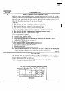
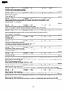
PIN NO. 1 19,20
Seqment data signal.
Signal similar to E6.
1 SIGNAL j El 8,E19
I
I/O
j OUT
(RD939A2U)
PIN NO. / 21-24
1 SIGNAL 1 E20-E23
I
I/O
; OUT
Used for initial balancing of the bridge circuit(absolute himidity sensor).
(RD936Al U)
PIN NO. ) 25
1 SIGNAL j EX
I
l/O
IN
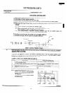
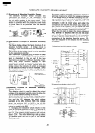
Internal clock oscillation frequency input settinq.
The internal clock frequency is set by inserting the ceramic filter oscillation circuit with respect to X terminal.
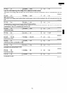
PIN NO. j 26
1 SIGNAL j X
Internal clock oscillation frequency control output.
Output to control oscillation input of EX.
PIN NO. j 27
Auto clear terminal.
(RD93EA2U)
I
I/O
/ OUT
(RD93EAl U)
1 SIGNAL /
RESET
I
I/O
1 IN
Signal is input to reset the LSI to the initial state when power is supplied.
Temporarily set to “L” level the moment power is supplied, at this time the LSI is reset,
Thereafter set at “H” level.
(RD93MA2U)
PIN NO. 1 28
1 SIGNAL / SO E24
I
I/O
/ OUT
Segment data siqnal.
Signal similar to E6.
(RD939A2U)
24