


R-8580
ABSOLUTE HUMIDITY SENSOR CIRCUIT
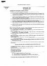
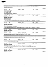
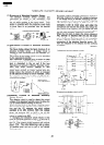
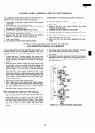
(1) Structure of Absolute Humidity Sensor
The absolute humidity sensor includes two
thermistors as shown in the illustration. One
thermister is housed in the closed vessel filled with
dry air while another in the open vessel. Each
sensor is provided with the protective cover made
of metal mesh to be protected from the external
airflow.
Internal Structure of Sensor
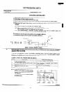
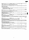
(2) Operational Principle of Absolute Humidity
Sensor
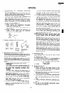
The figure below shows the basic structure of an
absolute humidity sensor. A bridge circuit is
formed by two thermistors and two resistors (Rl
and R2).
The output of the bridge circuit is to be amplified
by the operational amplifier.
Each thermister is supplied with a current to keep
it heated at about 150 “C (302 “F) and the resultant
heat is dissipated in the air and if the two
thermistors are placed in different humidity condi-
tions they show different degrees of heat
conductivity leading to potentiaJ difference be-
tween them causing an output voltage from the
bridge circuit, the intensity of which is increased
as the absolute humidity of the air increases. Since
the output is very minute, it will be amplified by the
operational amplifier.
C
Operational
RI
amplifier
T
output
I
vottaga
GIP-
-
.
sit : RI -
S: Thhenms
R3
C: Thermistor
closed vessl
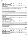
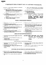
IDetector Circuite of
Sensor Circuit
t
Absolute humidity vs.
output voltage characteristic
H
=
e
5
0.
2
\JJj\i
1
b
Absolute humidity (g/m’ 1
Absolute Humidity
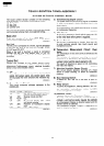
This detector circuit is used to detect the output
voltage of the absolute humidity circuit to allow the
LSI to control sensor cooking of the unit.
When the unit is set in the sensor cooking mode,
16 seconds later the detector circuit starts to func-
tion and the LSI observes the initial voltage
availabel at its AN2 terminal. With this voltage
given, the switches SW1 to SW5 in the LSI are
turned on in such a way as to change the resistance
values in parallel with R50.
-1. Changing the resistance values results in that
there is the same potential at both F-3 terminal of
the absolute humidity sensor and AN3 terminal of
the LSI. The voltage of AN2 terminal will indicate
about -2.5V. This initial balancing is set up about
16 seconds after the unit is put in the Sensor
Cooking mode.
As sensor cooking proceeds, the food is heated to
generate moisture by which the resistance balance
of the bridge circuit to deviate increasing the volt-
age available at AN2 terminal of the LSl. Then the
LSI observes that voltage at AN2 terminal and
compares it with its initial value, and when the
comparison rate reaches the preset value (fixed for
each menu to be cooked), the LSI causes the unit
to stop sensor cooking; thereafter, the unit goes
into the next necessary operation automatically.
When the LSI starts to detect the initial voltage at
AN2 terminal 16 seconds after the unit has been
put in the Sensor Cooking mode, if it is im possible
to take a balance of the bridge circuit due to dis-
connection of the absolute humidity sensor, ER-
ROR will reappear on the display and the cooking
is stopped.
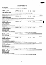
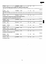
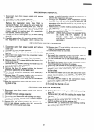
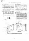
(RD72001 U)
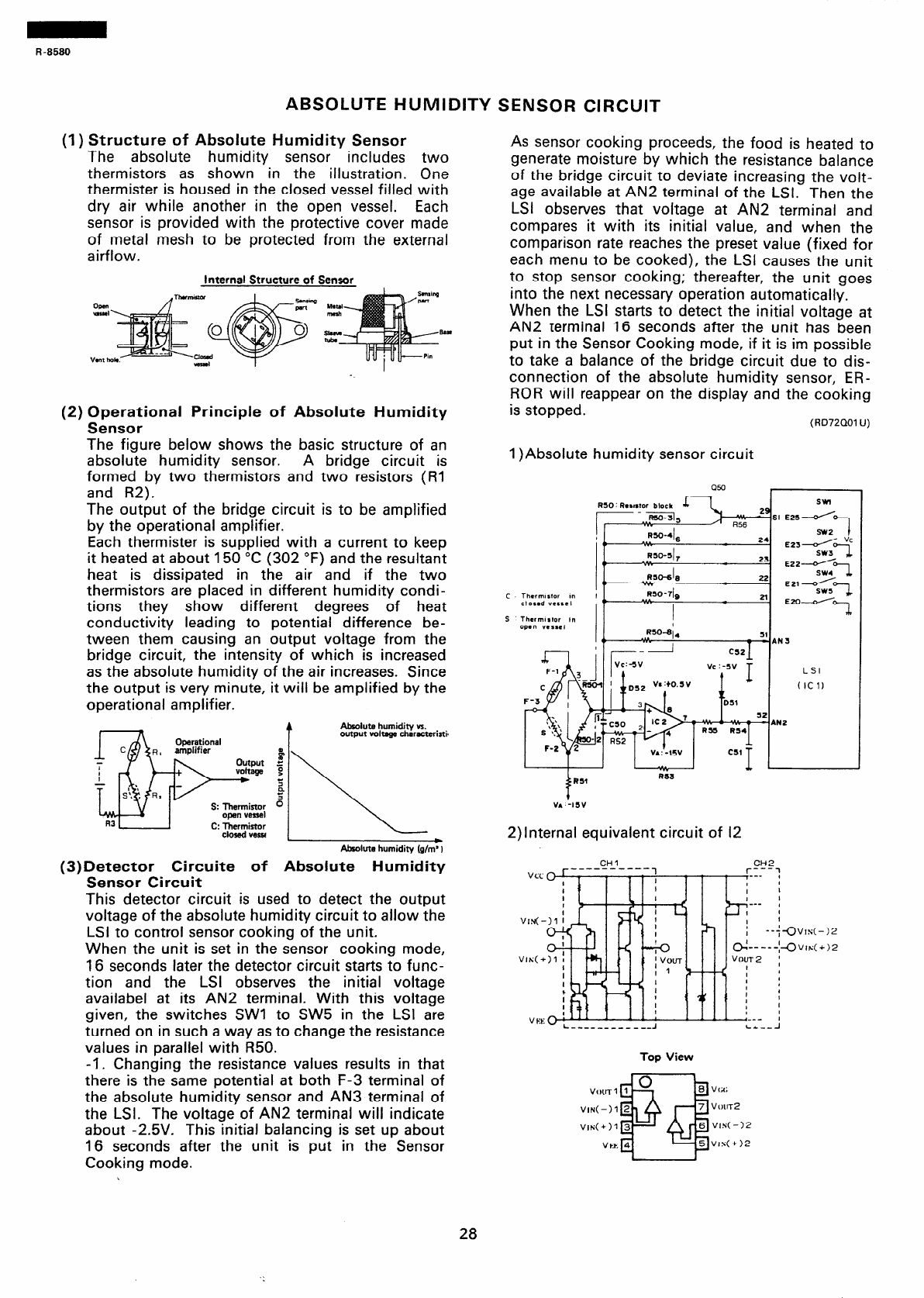
1 )Absolute humidity sensor circuit
Q!3l
RSO R.watOr Block
swt
-.,mJ
! *.*
I,
RsO-4)6
24
E23d “’
0
RSO-III7
23
SW301
E22^I
RSO&
22
SW47
0
”
EZl/
c
Thcrmlrtor m
RSO-7&
2l
WC-J
closed vessel
,C
c.
I
_ ma--I
7
S Thcrmlrtor In
open vessel
2)lnternal equivalent circuit of 12
Top View
28