


R -8580
COMPONENT REPLACEMENT AND ADJUSTMENT PROCEDURE
WARNING: To avoid possible exposure to microwave
4. There is any defective parts in the interlock,
A.
B.
1.
2.
3.
4.
5.
energy;
Before operating the oven
oven door or microwave generating and trans-
mission assemblv.
1.
2.
Do
the
1.
2.
3.
Make sure that unlatching the door slowly is
accompanied by a click indicating actuation of
the monitor switch and latch switches.
Check visually the door seal for arcing and
damage.
not operate the oven until after repair if any of
following conditions exist;
Door does not close firmly against the front of
appliance.
There iS a broken door hinge or support.
The door is bent or warped.
-
5.
------ ---I.
There is any other visible damage to the oven.
C. Do not operate the oven
1. Without the RF gasket.
2. If the door is not closed.
CAUTION: DISCONNECT OVEN FROM POWER
SUPPLY
BEFORE
REMOVING
OUTER CASE. DISCHARGE HIGH
VOLTAGE CAPACITOR
BEFORE
TOUCHING ANY OVEN COMPO-
NENTS OR WIRING.
(RDA? 203U)
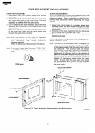
POWER TRANSFORMER REMOVAL
Disconnect oven from power supply and remove
3.
outer case.
Discharge high voltage capacitor.
Disconnect filament leads of transformer from the
magnetron.
Disconnect wire leads from the transformer.
Remove two (2) screws and one (I) washer hold-
ing the transformer to the cabinet base.
4.
5
Re-install
1.
2.
1.
2.
3.
4.
I.
2.
3.
4.
::
3.
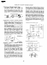
Rest the transformer on the base cabinet with its
primary terminals toward rear cabinet.
Insert the two edges of the transformer into two
metal tabs of the base cabinet.
6.
Make sure the transformer is mounted correctly
to the corners underneath those tabs
After re-installing the transformer, secure the
transformer with two screws to the cabinet base,
one is with outertooth washer and the other is
without outer-tooth washer.
Re-connect the wire leads (primary and high
voltage) to the transformer and filament leads of
transformer to the magnetron, referring to the
“Pictorial Diagram”.
Re-install the outer case and check that the oven
is operating properly.
HIGH VOLTAGE RECTI
Ii FIER REMOVAL
outer case.
Disconnect oven from power suppply and remove
Discharge the high voltage capacitor.
Remove one (1) screw holding the rectifier to the
capacitor holder.
Disconnect the rectifier from the capacitor.
RECTIFIER, THE GROUND SIDE
CAUTION: WHEN REPLACING THE SILICON
TERMINAL MUST BE SECURED
FIRMLY WITH A GROUNDING
SCREW.
HIGH VOLTAGE CAPACITOR REMOVAL
Disconnect oven from power supply and remove
outer case.
Discharge the high voltage capacitor.
Disconnect the high voltage wire leads from high
voltage capacitor.
Remove one (1) screw holding capacitor mounting
bracket.
5. Disconnect rectifier and high voltage rectifier from
the capacitor. .br
6. Remove one (1) screw holding the high voltage
rectifier and the capacitor holder.
7. Remove the capacitor from the holder.
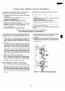
TURNTABLE MOTOR AND/OR COUPLING REMOVAL
Disconnect the oven from power supply.
Remove one (I ) screw holding the turntable motor
cover to the base cabinet and take off the turntable
motor cover.
Disconnect 2-pin connector from the turntable mo-
tor.
4.
5
6.
Remove the two (2) screws holding the turntable
motor to the mounting plate of the oven cavity.
Pull the turntable coupling out of the oven cavity.
The turntable motor is now free.
30