


1.
2.
3.
4.
5.
5.
6.
8.
9.
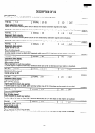
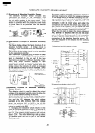
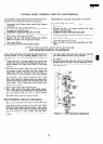
MAGNETRON REMOVAL
Disconnect oven from power supply and remove
outer case.
screws, a carefull attention should be necessary to
Discharge the high voltage capacitor.
prevent the magnetron fall away.
Disconnect wire leads from the magnetron.
6. Remove the magnetron (with magnetron cooling
Remove the magnetron temp. fuse fitted to
duct(B)) from the unit with a careful attention the
waveguide flange. And release the wire leads from
magnetron tube should not hit by any metal object
around the tube.
the hole of magnetron cooling duct (B). And re-
lease the AH sensor harness from hole of chassis
support.
Remove four (4) screws holding the
chassis support to cooling duct (A), waveguide,
rear cabinet, control back plate.
7. Remove one (1) screw holding cooling duct (B) to
the magnetron.
8. Remove cooling duct (B) from the magnetron.
9. Now the magnetron is free.
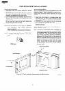
CAUTION:
Release the tab on cooling duct (B) to hold cooling
duct (A).
Carefully remove four (4) mounting screws holding
the magnetron to waveguide, when remove the
WHEN REPLACING THE MAGNETRON,
BE SURE THE R.F. GASKET IS IN
PLACE
AND THE MAGNETRON
MOUNTING SCREWS ARE TIGHTENED
SECURELY.
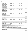
CONVECTION MOTOR REMOVAL
Disconnect oven from power supply and remove
outer case.
Disharge the high voltage capacitor.
Remove sliding the thermal cut-out with its wire
lead on.
Disconnect wire leads from the convection motor
and convection heater.
Disconnect the 2-pin connector from thermistor.
Remove eleven (11) screws holding the heater duct
to the oven cavity.
Remove two (2) screws holding the heater duct to
thermal protection plate (bottom).
The heater unit is now free.
Remove the four (4) screws holding the thermal
protection plate(left) to the heater duct.
1 O.The thermal protection plate(left) and sheet( left)
are now free.
11 .Remove three (3) screws holding the convection
motor mounting plate to the heater duct.
12.Pull the convection motor shaft out of convection
fan.
13.Now the convection motor with the motor mount-
ing plate is free.
1.
2.
3.
4.
5.
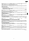
14.Remove two (2) nuts holding the motor mounting
plate to the convection motor.
15.Convection motor is now free.
Re-install
1. Re-install the convection motor mounting plate to
the convection motor by the two (2) nuts.
2. Put the convection fan to the motor shaft.(fit with a
E-ring.)
3. Re-install the heater duct to the convection motor
mounting plate by the three (3) screws.
4. Make sure the rotation of the convection motor.
5. Re-install the thermal protection plate to cover the
heatewr duct with sandwiching the thermal pro-
tection sheet.
6. Re-install the heater unit to the left side of the oven
cavity by the eleven (11) screws.
Re-install the
heater unit to thermal protection plate (buttom) by
two (2) screws.
7. Re-install the wire leads to the convection motor,
convection heater, thermister connector.
Refering to “Pictorial diagram”.
8. Re-install the thermal cut-out.
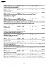
COOLING FAN MOTOR REMOVAL
Disconnect oven from power supply and remove
outer case.
Discbarge the high voltage capacitor.
Disconnect wire leads from the cooling fan motor.
Release AH sensor harness from chassis support
and cooling duct (A).
Remove four (4) screws holding the chassis sup-
port to rear cabinet, cooling duct
flange and control panel back plate.
(A), waveguide
6. Release the tab on cooling duct (B) holding cooling
duct (A). -
7. Remove duct (A) with the cooling fan motor from
the unit.
The cooling fan motor assembly is now free.
8. Remove the fan blade from the cooling fan motor
shaft by pulling out the fan retainer clip.
9. Remove two (2) screws and nuts holding cooling
fan motor to the cooling duct (A).
The cooling fan motor is now free.
31