


R -8580
DOOR REPLACEMENT AND ADJUSTMENT
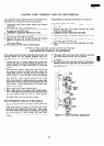
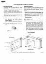
DOOR REPLACEMENT
1. Disconnect oven from power supply and remove
outer case.
2. Holding the door, remove three (3) screws securing
the upper door hinge to the oven cavity. The door
assembly is nowfree from the oven cavity.
3. On re-installing new door assembly, secure the door
assembly with the three (3) mounting screws to the
oven cavity.
Make sure the door is parallel with the bottom line
of the oven face plate and the latch heads pass
through the latch holes correctly.
Note: After any service to the door, .-an approved
microwave survey meter should be used to as-
sure
compliance
with proper
microwave
rediation standard.
(Refer to Microwave Measurement Procedure).
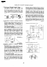
Note: If the Latch Heads Need Removal, “TORX T-20”
or “LHXTIX LR-3” Type screwdriver should be
used.
TORX screw
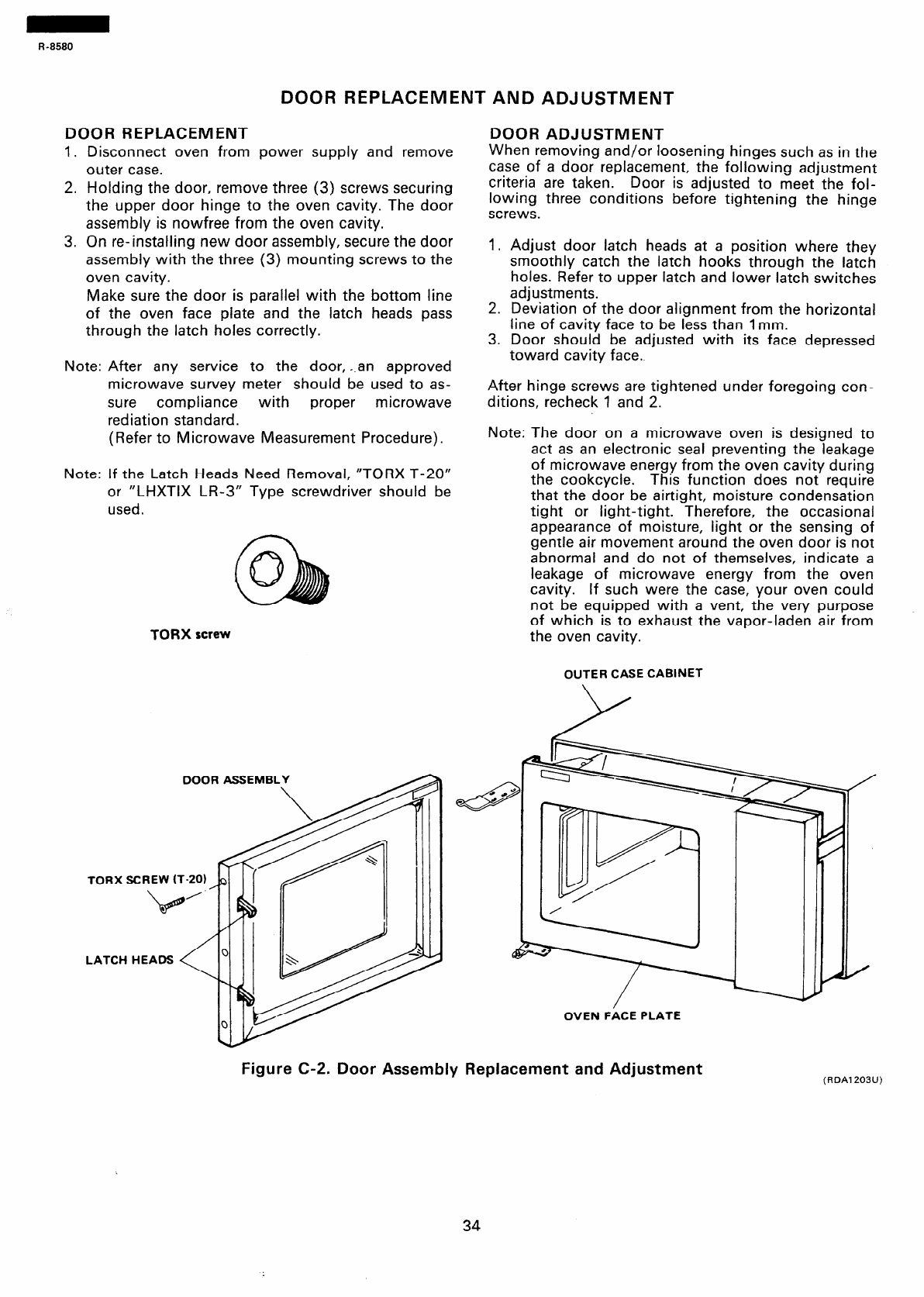
DOOR ASSEMBL
TORX SCREW
(T-20)
LATCH HEADS
DOOR ADJUSTMENT
When removing and/or loosening hinges such as in the
case of a door replacement, the following adjustment
criteria are taken.
Door is adjusted to meet the fol-
lowing three conditions before tightening the binge
screws.
I. Adjust door latch heads at a position where they
smoothly catch the latch hooks through the latch
holes. Refer to upper latch and lower latch switches
adjustments.
2. Deviation of the door alignment from the horizontal
line of cavity face to be less than 1 mm.
3. Door should be adjusted with its face depressed
toward cavity face.
After hinge screws are tightened under foregoing con-
ditions, recheck 1 and 2.
Note: The door on a microwave oven is designed to
act as an electronic seal preventing the leakage
of microwave energy from the oven cavity during
the cookcycle.
This function does not require
that the door be airtight, moisture condensation
tight or light-tigbt. Therefore, the occasional
appearance of moisture, light or the sensing of
gentle air movement around the oven door is not
abnormal and do not of themselves, indicate a
leakage of microwave energy from the oven
cavity. If such were the case, your oven could
not be equipped with a vent, the very purpose
of which is to exhaust the vapor-laden air from
the oven cavity.
OUTER CASE CABINET
OVEN FACE PLATE
Figure C-2. Door Assembly Replacement and Adjustment
(RDA1203U)
34