


OPTIONAL ACCESSORIES
Battery Power Supply
...........................................................................
Output Cable Kit
..................................................................................
Locking Panel
........................................................................................
Phono Preamp
........................................................................................
Rack Panel Kit
.....................................................................................
Stacking Kit
...........................................................................................
Interconnecting Cable
...........................................................................
Attach6 Case
..........................................................................................
Model A68B
Model A68C
Model A68L
Model A68P
Model A68R
Model A68S
Model A68SC
Model AC68
SPECIFICATIONS
Gain: At 1,000
Hz.
(cps).
outputs
Low Imp.
High Imp. High Imp.
Input Mic.
Mic. Aux.
Low Imp. Mic.
f9
db +33 db +60 db
.5 mv produces 1.4 mv 22 mv 500 mv
High Imp. Mic. -13 db
fll
db 4-38 db
5 mv produces 1.1 mv 18 mv 400 mv
AUX. -35 db -11 db f16 db
50 mv produces
0.9
mv 14 mv 320 mv
ii3f8
12889mml-I
I
n
I
u-
---
-\
1-
IV
-
--$32
aPPnoxU
UJ
(5
5mm)
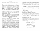
OVER
ALL
DIMENSIONS
-
FIGURE
B
Frequency Response: The frequency response is flat &f:b from
,30
Hz. (cps)
to 20,000 Hz. (cps)
.
Hum-Noise:
Equivalent Input Noise: 150 ohm source, 123 db below 1 volt.
Input Impedance: Microphone inputs suitable for high
or
low impedance dynamic
and ribbon microphones. Auxiliary-50,000 ohms.
Recommended Load Impedance:
2
fLO
7
70
db below rated output.
Low Impedance Microphone
.................................................
25 to 600 ohms
High Impedance Microphone
................................................
20,000 ohms or greater
Auxiliary High Impedance
.....................................................
50,000 ohms or greater
Distortion: Less than 1
%
total Harmonic Distortion when low impedance micro-
phone output is at 20 mv level, high impedance microphone output is at 200 mv
level, and
Aus.
high impedance output is at 2.0 volt level.
Output Clipping Level:
output Min. Clipping Level
Mic. Low Impd.
60
mv
Mic. High Impd. .85 volts
Aux. High Impd.
4.0
volts
Operating Voltage
:
Model M68: 105-130 volts 50/60 cycle
Models M68-2 and M68-2E: 105-130 volts 50/60 cycle or 210-240 volts 50/60
cycle.
Case: Painted Metal.
Dimensions: See Figure B.
Net Weight: 4 pounds.
27A477
(I
1-67)
Copyright
1967,
Shure
Brothers,
Inc.
222
HARTREY
AVE
EVANSTON,
ILL.
(60204)
U.S.A.
AREA CODE
312/328-9000
'
CABLE SHUREMICRO
MODELS
M68,
M68-2,
AM)
M68-2E MICROPHONE MIXERS
lk
I?
*'?
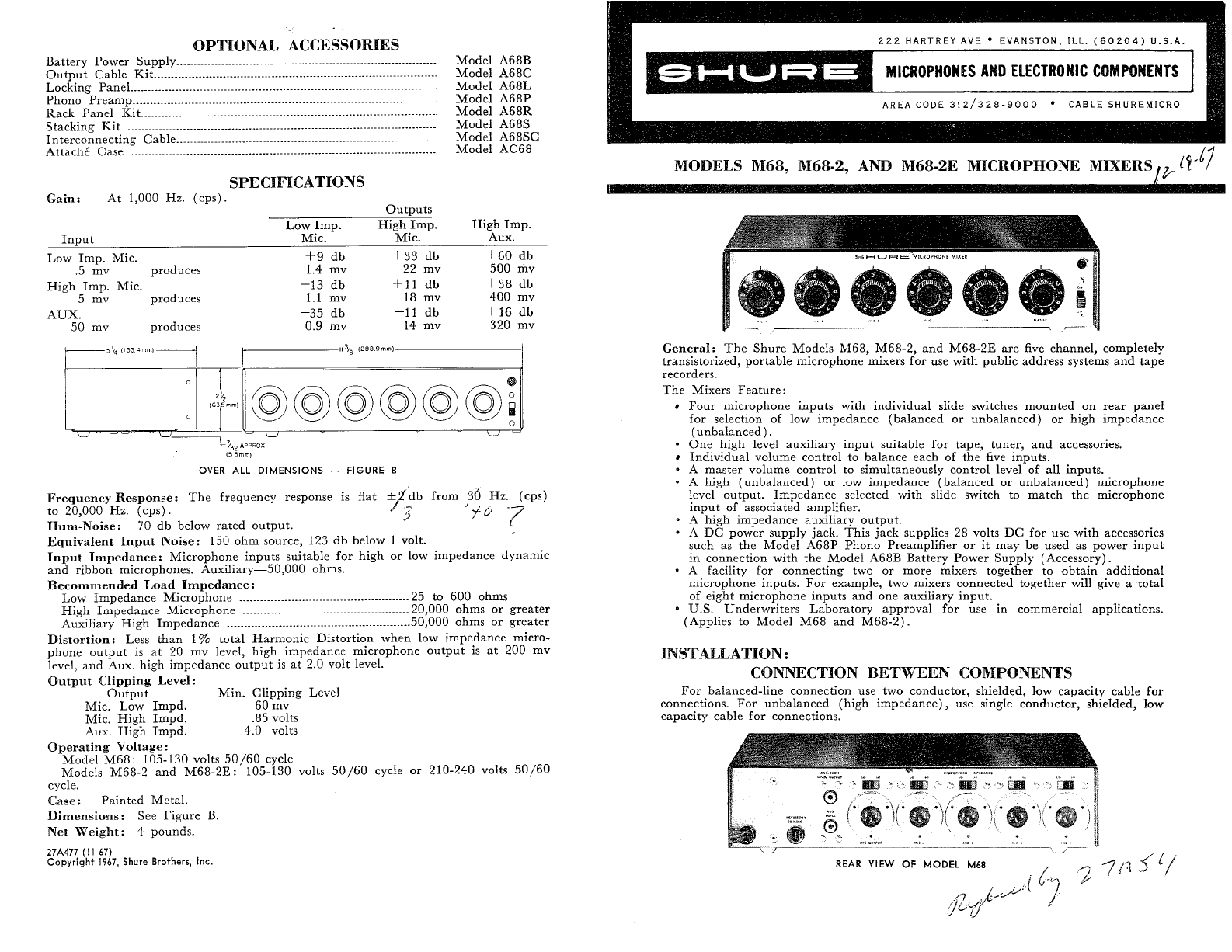
General: The Shure Models M68, M68-2, and M68-2E are five channel, completely
transistorized, portable microphone mixers for use with public address systems and tape
recorders.
The Mixers Feature:
Four microphone inputs with individual slide switches mounted on rear panel
for selection of low impedance (balanced or unbalanced) or high impedance
(unbalanced).
One high level auxiliary input suitable for tape, tuner, and accessories.
Individual volume control to balance each of the five inputs.
*
A master volume control to simultaneously control level
of
all inputs.
*
A high (unbalanced)
or
low impedance (balanced or unbalanced) microphone
level output. Impedance selected with slide switch to match the microphone
input of associated amplifier.
*
A high impedance auxiliary output.
A DC power supply jack. This jack supplies 28 volts DC for use with accessories
such
as
the Model A68P Phono Preamplifier
or
it may be used
as
power input
in connection with the Model A68B Battery Power Supply (Accessory).
*
A facility
for
connecting two or more mixers together to obtain additional
microphone inputs.
For
example, two mixers connected together will give
a
total
of eight microphone inputs and one auxiliary input.
0
U.S.
Underwriters Laboratory approval for use in commercial applications.
(Applies to Model M68 and M68-2).
INSTALLATION
:
CONNECTION BETWEEN COMPONENTS
For balanced-line connection use two conductor, shielded, low capacity cable
for
connections. For unbalanced (high impedance), use single conductor, shielded, low
capacity cable for connections.