


20
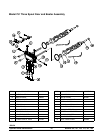
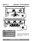
Models 750, 751, 754, 774, 791, 794Important: To the Operator
091030
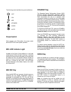
Reset Button
On counter models, the reset button is located on the
side of the unit. On console models, the reset button
is located in the service panel. The reset protects the
beater motor from an overload condition. If an overload
occurs, the reset mechanism will trip. To properly reset
the freezer, press the AUTO key to cancel the cycle.
T urn the power switch to the OFF position. Press the
reset button firmly.
Do not use metal objects to press the reset
button. Failure to follow this instruction may
result in electrocution.
T urn the power switch to the ON position. Press the
W ASH key and observe the freezer’s performance.
Open the side access panel. Make sure the beater
motor is turning the d rive shaft in a clockwise direction
(from the operator end) without binding.
If the beater motor i s turning properly, press the WASH
key to cancel the cycle. Press the AUTO key to resume
normal operation. If the freezer shuts down again,
contact a service technician. ( For Models 754, 774,
791, and 794 press the AUTO key on both sides of the
unit to resume normal operation.)
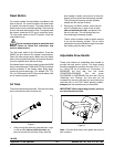
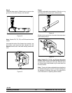
Air Tube
The air tube serves two purposes. One end of the tube
has a hole and the other end does not.
Figure 1
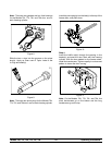
1. A fter priming the machine, lubricate the o--rings
on the a ir tube (the end with the hole) and
place it into the mix inlet hole. Every time the
draw handle is raised, new mix and air from the
hopper will flow down into the freezing cylinder.
This will keep the freezing cylinder properly
loaded and will maintain overrun.
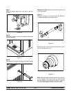
2. Dur ing long “No Sale” periods, remove the air
orifice. Lubricate the o--rings on the air tube
(the end without the hole), and place it into
the mix inlet hole. This will prevent any mix
from entering the freezing cylinder.
The air orifice is used to meter a certain amount
of air into the freezing cylinder. The air orifice
maintains overrun and allows enough mix to enter
the freezing cylinder after a draw .
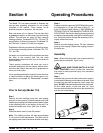
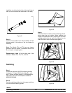
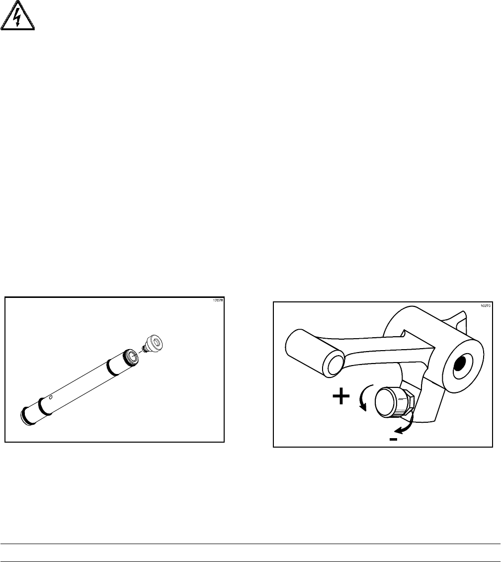
Adjustable Draw Handle
These units feature an adjustable draw handle to
provide the best portion control. The draw handle
should be adjusted to provide a flow rate of 5 to 7--1/2
oz. (148 to 222 ml) of product per 10 seconds. To
INCREASE the flow rate, turn the screw
COUNTERCLOCKWISE. Turn the screw
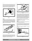
CLOCKWISE to DECREASE the f low rate. During
“Sanitizing” and “Rinsing”, the flow rate can be
increased by removing the pivot pin and placing the
restrictive bar on the TOP. When drawing product,
always place the restrictive bar on the bottom.
IMPORTANT! When dispensing product, pull only
one draw handle at a time.
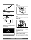
Figure 2
Note: Once the d raw rate is set, tighten the lock nut
with a wrench.