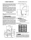
VII. e - FRONT WORK SURFACE REMOVAL :
To facilitate transport through narrow doorways all
Jumbo Rail VPS models are supplied standard with a
removable front work surface (see figure 10).
WARNING: Excess weight hazard. Use two or more
people and to remove and reinstall. Failure to do so
can result in damage to the unit and/or injury.
1) Remove the side cover (held in place by two screws)
from each side.
2) Remove the screw from each side.
3) Remove the screws under the work surface, above
the louver and hinged doors.
4) Support the work surface securely then remove the
screws from the vertical lip at the rear of the work
surface.
5) Lift the work surface up and away from the cabinet.
Reinstall in reverse order and seal the perimeter with
silicone.
VII. SERVICE & MAINTENANCE INFORMATION (cont’d)
-7-
Remove the stainless
steel side brackets
from each side.
Lift work surface up
and away from unit
when all screws are
removed.
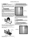
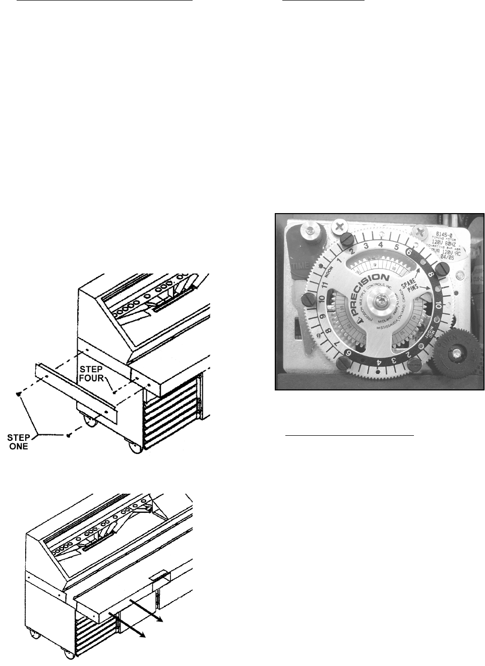
VII. f - DEFROST TIMER:
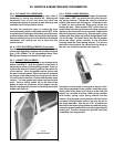
In normal operation the defrost timer only needs to be
set on startup and after each power loss. Rotate the
small knob (near the outer edge of the large dial)
clockwise until the correct time of day on the large dial
is opposite the TIME pointer. Pins that initiate each
defrost cycle are set at the factory at 2am, 6am, 10am,
2pm and 8pm. If your operation requires different
defrost times simply relocate one or more of the pins
(around the outer edge of the large dial) to the
appropriate time. Leave four hours minimum time
between pins. A minimum of five (5) defrost cycles are
required per day. Defrost is terminated by a non-
adjustable temperature-activated switch located in the
evaporator housing. The bronze pointer on the inner
dial controls the time-activated backup termination and
should not be changed from the factory setting of 30
minutes.
VII. g - TEMPERATURE CONTROL:
The electronic temperature control is set at the factory
and needs no adjustment in normal use.
Reprogramming is not necessary even if the power is
interrupted. If the control has to be replaced, verify
that the settings match the original factory settings. See
below for factory settings.
The control is equipped with a lockout switch to
prevent unauthorized tampering. VPS units are shipped
from the factory with this switch in the LOCK position,
with the keypad disabled.
To check or change the settings:
Turn the power switch OFF then loosen the 4 screws
that hold the control cover in place. The lockout switch
is located on the inside cover about two inches above
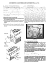
the bottom (see figure 12). To enable the keypad, slide
the switch to the right (UNLOCK) position. Replace the
control cover and turn the power switch ON. Always
disable the keypad by moving the switch to left (LOCK)
position after checking the settings.
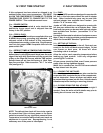
Fig. 10
Removing the
Work Surface
Fig. 11
Defrost Timer


