


ENGLISH
Installation Manual
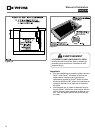
10
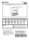
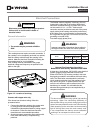
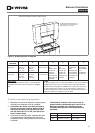
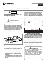
Recommended Minimum
kW Rating on
serial plate
Circuit protection
in amperes
Wire size
(AWG)
0-4.8
20 12
4.9-6.9
30 10
7.0-9.9
40 8
10.0-11.9
50 8
12.0-14.9
60 6
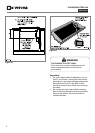
Be sure your appliance is properly installed and
grounded by a qualified technician. Ask your
dealer to recommend a qualified technician or an
authorized repair service. This cooktop does not
require a neutral connection. If the cooktop Is to
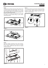
be completely enclosed In a cabinet, feed the
cooktop cable through the opening in the cabinet.
Make the electrical connection following the
appropriate steps for your installation.
This appliance is manufactured with a green ground
wire connected to the cooktop chassis. After making
sure that the power has been turned off, connect the
flexible conduit from the cooktop to the junction box
using a U.L. listed conduit connector. Figures 13 and
14 and the instructions provided below present the
most common way of connecting the cooktops. Your
local codes and ordinances, of course, take
precedence over these instructions. Complete
electrical connections according to local codes and
ordinances
DANGER
Risk of Electric Shock, frame grounded to
neutral of appliance through a link.
Grounding through the neutral conductor is prohibited
for new branch-circuit installations (1996 NEC);
mobile homes; and recreational vehicles, or in an area
where local codes prohibit grounding through the
neutral conductor.
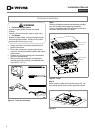
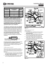
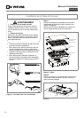
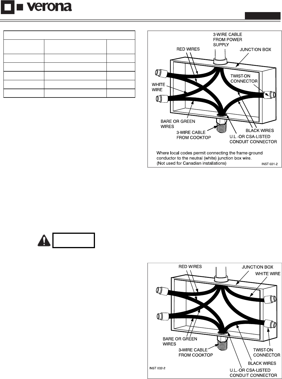
3-Wire branch circuit
Where local codes allow the connection of ground
wire from the cooktop to the branch circuit neutral wire
(gray or white colored wire) proceed as follows (see
figure 13).
1. If local codes permit, connect the green GROUND
wire from the cooktop to the branch circuit neutral
wire (gray or white colored wire).
2. Connect the red and black leads from the cooktop
to the corresponding leads in the junction box.
Figure 1.
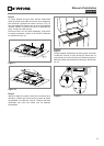
4-Wire branch circuit
Refer to figure 14:
1. Connect the green ground wire from the cooktop
to the ground wire in the junction box (bare or
green colored wire).
2. Connect the red and black leads from the cooktop
to the corresponding leads in the junction box.
3. Connect the white wire from the cooktop to the
neutral (gray or white) wire in the junction box.
4. Terminate and insulate the neutral (gray or white
colored wire) in the junction box.
Figure 1.