VHX SERIES STEAMER - ELECTRICAL OPERATION
F24700 (October 2001) Page 44 of 68
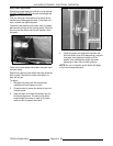
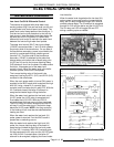
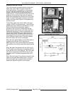
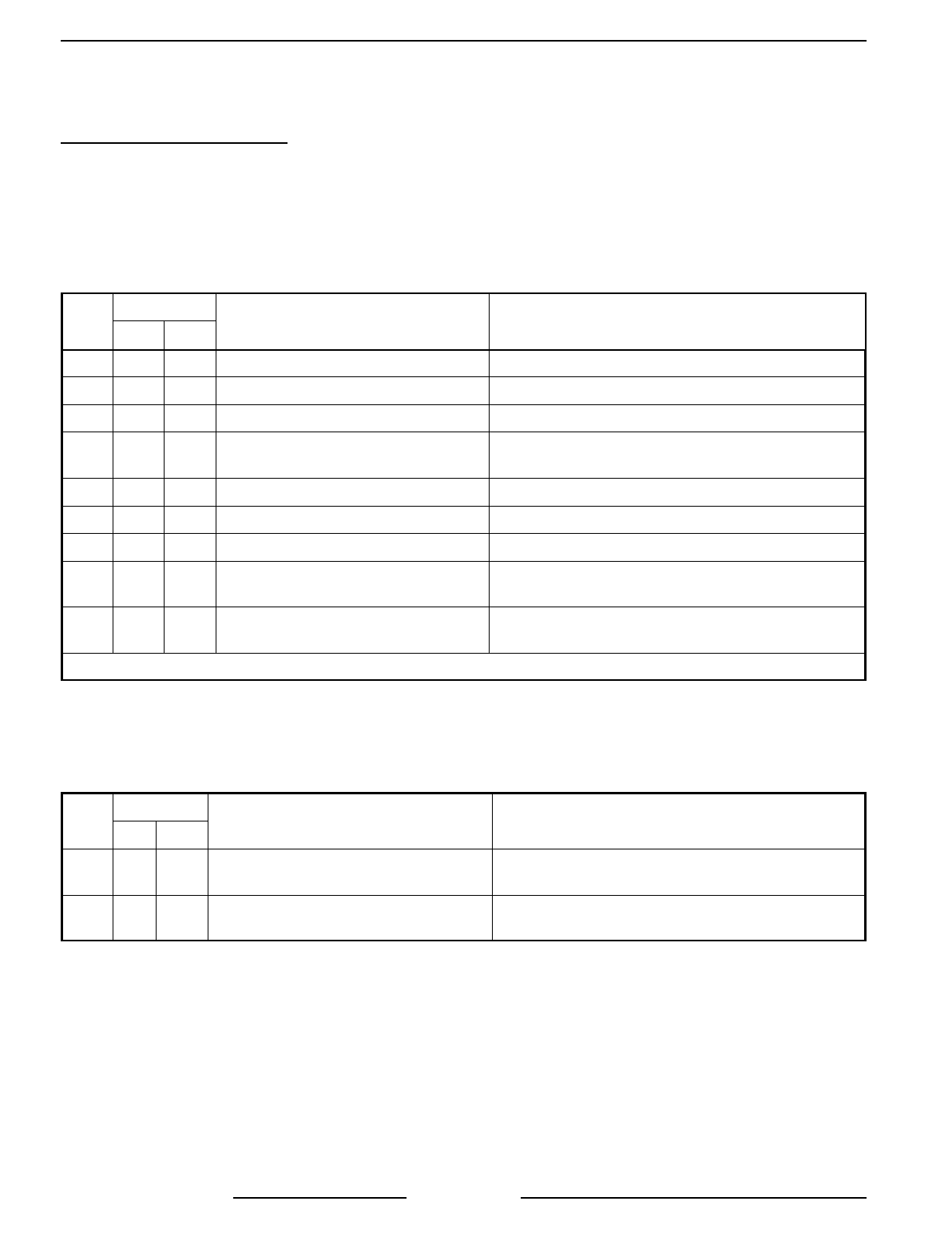
Boiler Operational Status (LED Indicator)
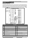
Use the tables below to determine the operational status of a component or condition by utilizing the LED
indicators on the board. The operational state’s are divided into categories A thru F.
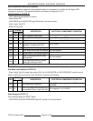
Initial Conditions: (STATE A)
- 120V, water and gas supplied to steamer
- Power Switch ON
- HIGH PRESS and LOW WATER lights ON (amber, front control panel)
- Green “ready” light OFF
- Water is filling boiler
LED
STATUS
DESCRIPTION ELECTRICAL COMPONENTS CONDITION
ON OFF
N1 X 24V supplied to relay board
N2 X Aux Water level not satisfied Aux. LLCO contacts OPEN
N3 X High limit pressure switch satisfied K2 energized - K2(1) CLOSE, K2(2) CLOSE
N4 X
Aux Water level is initially not
satisfied. Therefore N4 is OFF
K1(1) OPEN
N5 X Reset switch is not being energized
N6 X Aux Water level is/was not satisfied K3 not energized
N7 X Reset switch is not being energized
N8 X
High Limit pressure switch is/was
not satisfied
K4 not energized
N9 X
Cycling pressure switch is closed
and unit is calling for HEAT
N10 through N17 remain OFF
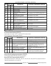
Aux Water Level Satisfied: (STATE B)
- Green “ready” light ON (ready light remains ON, until a LOW WATER or HIGH PRESSURE) condition occurs.
Status of LED’s are the same as “Initial Conditions” except for the following:
LED
STATUS
DESCRIPTION ELECTRICAL COMPONENTS CONDITION
ON OFF
N2 X Aux water level is satisfied
Aux. LLCO relay energized, Aux. LLCO contacts
CLOSED
N4 X
Aux LLCO water level and high limit
are satisfied. Green “ready” light ON.
K1 energized - K1(1) CLOSE
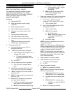
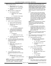
Reset Engaged: (STATE C)
User presses/engages the RESET button
- LOW WATER and HIGH PRESSURE lights OFF (amber, front control panel)


