


F
n
FOR MOBILE HOME USE, A 4-WIRE
POWER CORD MUST BE USED. This
appliance is manufactured with ground
connected to cabinet. The ground must
be revised so the green grounding wire of
the 4-wire power cord is connected to
the cabinet. See 4-wire electrical
connection section, Panel C.
If using a 4-wire NEMA type 14-50R
receptacle, a matching 4-wire U.L.-listed
“pigtail” power cord must be used. Cord
should be type SRD or SRDT, at least
4 feet long and have all conductors
ending in ring terminals at the range. See
Figure 2. The MINIMUM conductor sizes for
the copper 4-wire power cord are:
40 ampere circuit
2, No. 8 conductors
1, No. 10 white neutral
1, No. 8 green grounding
G
n
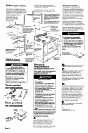
A wiring diagram is included in
literature package. The wiring diagram is
also located on the back of the range.
J-wire wall
4-wire wall
receptacle (lo-5OR)
receptacle (14~50R)
Figure 1
Figure 2
12
n
Connect the neutral (white)
3-wire electrical connection
See Panel C for 4-wire electrical
connection.
wire to the silver-colored terminal screw
on the terminal block. Connect the other
two wires to the outer terminal screws on
the terminal block. Use ring-type terminals
only. Check that nuts are tight to insure
proper electrical connection.
Now start...
With range in kitchen.
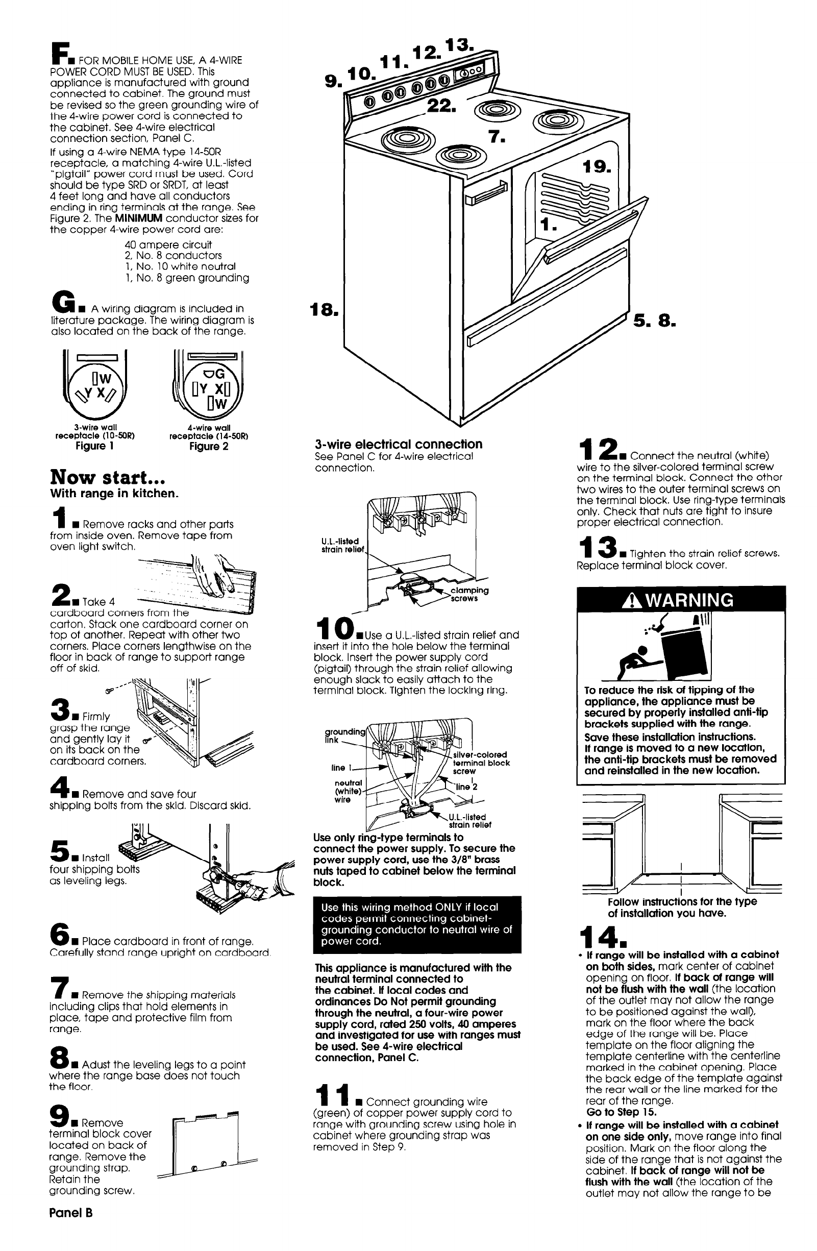
1
n
Remove racks and other parts
from inside oven. Remove tape from
oven light switch.
13
n
Tighten the strain relief screws.
U.L.-listed
strain relief
t
t
.k
/
Replace terminal block cover.
2
n
Take 4
cardboard corners fro
10
Muse a U-L.-listed strain relief and
“. .-
carton. Stack one cardboard corner on
top of another. Repeat with other two
corners. Place corners lengthwise on the
floor in back of range to support range
off of skid.
insert it into the hole below the terminal
block. Insert the power supply cord
(pigtail) through the strain relief allowing
enough slack to easily attach to the
terminal block. Tighten the locking ring.
To reduce the risk of tipping of the
appliance, the appliance must be
secured by properly installed anti-tip
brackets supplied with the range.
Save these installation instructions.
If range is moved to a new location,
the anti-tip brackets must be removed
and reinstalled in the new location.
‘H Firmly
grasp the range
and gently lay it
on its back on the
cardboard corners.
arounding
iink
-colored
terminal
I block
^ ^ .^. . .
SW wtn
&
line l*
4
n
Remove and save four
shipping bolts from the skid. Discard skid.
Use only rinY-type terminals to
connect the power supply. To secure the
power supply cord, use the 3/8” brass
nuts taped to cabinet below the terminal
block.
5
n
Install
four shipping
as leveling legs.
Follow instructions for the type
of installation you have.
6
n
Place cardboard in front of range.
Carefully stand range upright on cardboard
14.
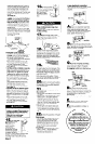
l
If range will be installed with a cabinet
on both sides, mark center of cabinet
opening on floor. If back of range will
not be flush with the wall (the location
of the outlet may not allow the range
to be positioned against the wall),
mark on the floor where the back
edge of the range will be. Place
template on the floor aligning the
template centerline with the centerline
marked in the cabinet opening. Place
the back edge of the template against
the rear wall or the line marked for the
rear of the range.
Go to Step 15.
l
If range will be installed with a cabinet
on one side only, move range into final
position. Mark on the floor along the
side of the range that is not against the
cabinet. If back of range will not be
flush with the wall (the location of the
outlet may not allow the range to be
This appliance is manufactured with the
neutral terminal connected to
the cabinet. If local codes and
ordinances Do Not permit grounding
through the neutral, a four-wire power
supply cord, rated 250 volts, 40 amperes
and investigated for use with ranges must
be used. See 4-wire electrical
connection, Panel C.
7
n
Remove the shipping materials
including clips that hold elements in
place, tape and protective film from
range.
8
n
Adust the leveling legs to a point
where the range base does not touch
the floor.
11
n
Connect grounding wire
(green) of copper power supply cord to
range with grounding screw using hole in
cabinet where grounding strap was
removed in Step 9.
terminal block cover
located on back of
range. Remove the
grounding strap.
Retain the
grounding screw.
Panel B