


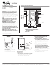
PRODUCT MODEL NUMBERS CABINET OPENING DIMENSIONS
GI15NDXT
GI15NFLT
GI15NFRT
Electrical: A 115 Volt, 60 Hz., AC only, 15- or
20-amp electrical supply, properly grounded in
accordance with the National Electrical Code and
local codes and ordinances is required.
It is recommended that a separate circuit, serving
only your ice maker, be provided. Use a receptacle
which cannot be turned off by a switch or pull
chain.
Water: A cold water supply with water pressure
of between 30 and 120 psi (207 and 827 kPa) is
required to operate the ice maker.
IMPORTANT: Reverse osmosis water filtration
systems can be used only with ice maker
installations that have a gravity drain. A reverse
osmosis system is not recommended for ice
makers that have a drain pump installed.
The pressure of the water supply coming out of a
reverse osmosis system going to the water inlet
valve of the ice maker needs to be between 30 and
120 psi (207 and 827 kPa).
Drain: Either a gravity-drain system or drain
pump system (on some models) to carry water to
an existing drain.
Because Whirlpool Corporation policy includes a continuous commitment to improve
our products, we reserve the right to change materials and specifications without notice.
Dimensions are for planning purposes only. For complete details, see Installation
Instructions packed with product. Specifications subject to change without notice.
Ref. W10136155B
07-28-08
®
11
¹⁄₂
"
(29.2 cm)
15"
A
B
(38.1 cm)
24"
(60.1 cm)
9"
(22.9 cm)
28
¹⁄₂
"
(72.4 cm)
34"
(86.4 cm)
Min.
34
¹⁄₂
"
(87.6 cm)
Max.
3
¹⁄₂
"
(8.9 cm)
A. Recommended location for electrical
and plumbing fixtures.
B. Floor level
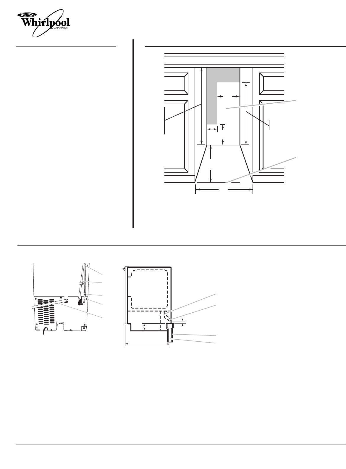
SIDE VIEW
A.Drain hose
B.1" (2.54 cm) air gap
C.PVC drain reducer
D.Center of drain should be 23" (58.4 cm) from front of door,
with or without the ³⁄₄" (1.91 cm) panel on the door. The
drain should also be centered from left to right (7
⁵⁄₁₆
"
[18.57 cm] from either side of the ice maker).
1⁷⁄₈"
(4.8 cm)
23"
(58.4 cm)
2" - 1¹⁄₂"
(5 cm - 3.8 cm)
1" (2.54 cm)
A
D
C
B
■ Drain lines must have a minimum of 5⁄8"
(15.88 mm) inside diameter.
■ Drain lines must have a 1" drop per 48"
(2.54 cm drop per 122 cm) of run or 1⁄4" drop
per 12" (6.35 mm per 30.48 cm) of run and
must not have low points where water can
settle.
■ The floor drains must be large enough to
accommodate drainage from all drains.
■ The ideal installation has a standpipe with a
1-1⁄2" (3.81 cm) to 2" (5.08 cm) PVC drain
reducer installed directly below the outlet of the
drain tube as shown. You must maintain a
1" (2.54 cm) air gap between the drain hose and
the standpipe.
■ It may be desirable to insulate the drain line
thoroughly up to the drain inlet.
DRAIN REQUIREMENTS
REAR VIEW
A.Water supply tube clamp
B.Vent hose (drain pump models only)
C.Water supply line
D.Inlet water tube clamp
E.Drain hose (drain pump models only)
A
C
D
E
B
Ice Maker