


6" (15.2 cm) vent system = 73 ft (22.2 m) total
A B
C
D
6 ft (1.8 m)
2 ft
(0.6 m)
A. Two 90° elbows = 20 ft (6.1 m)
B. 1 wall cap = 40 ft (12.2 m)
C. 1 rectangular to round transition
piece = 5 ft (1.5 m)
D. 2 ft (0.6 m) + 6 ft (1.8 m)
straight = 8 ft (2.4 m)
" (76.0 cm
)
15
"
(40.0 cm)
17
"
(43.8 cm)
16
"
(41.3 cm)
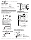
PRODUCT MODEL NUMBERS PRODUCT DIMENSIONS
VENTING REQUIREMENTS
Electrical: A 120-Volt, 60-Hz, AC-only, 15- or 20-amp fused electrical
supply with a fuse or circuit breaker. A time-delay fuse or time-delay circuit
breaker is recommended. It is recommended that a separate circuit serving
only this microwave oven be provided.
Microwave Hood Combination
Because Whirlpool Corporation policy includes a continuous commitment to improve
our products, we reserve the right to change materials and specifications without notice.
Dimensions are for planning purposes only. For complete details, see Installation
Instructions packed with product. Specifications subject to change without notice.
Ref. W10238252A
5/09
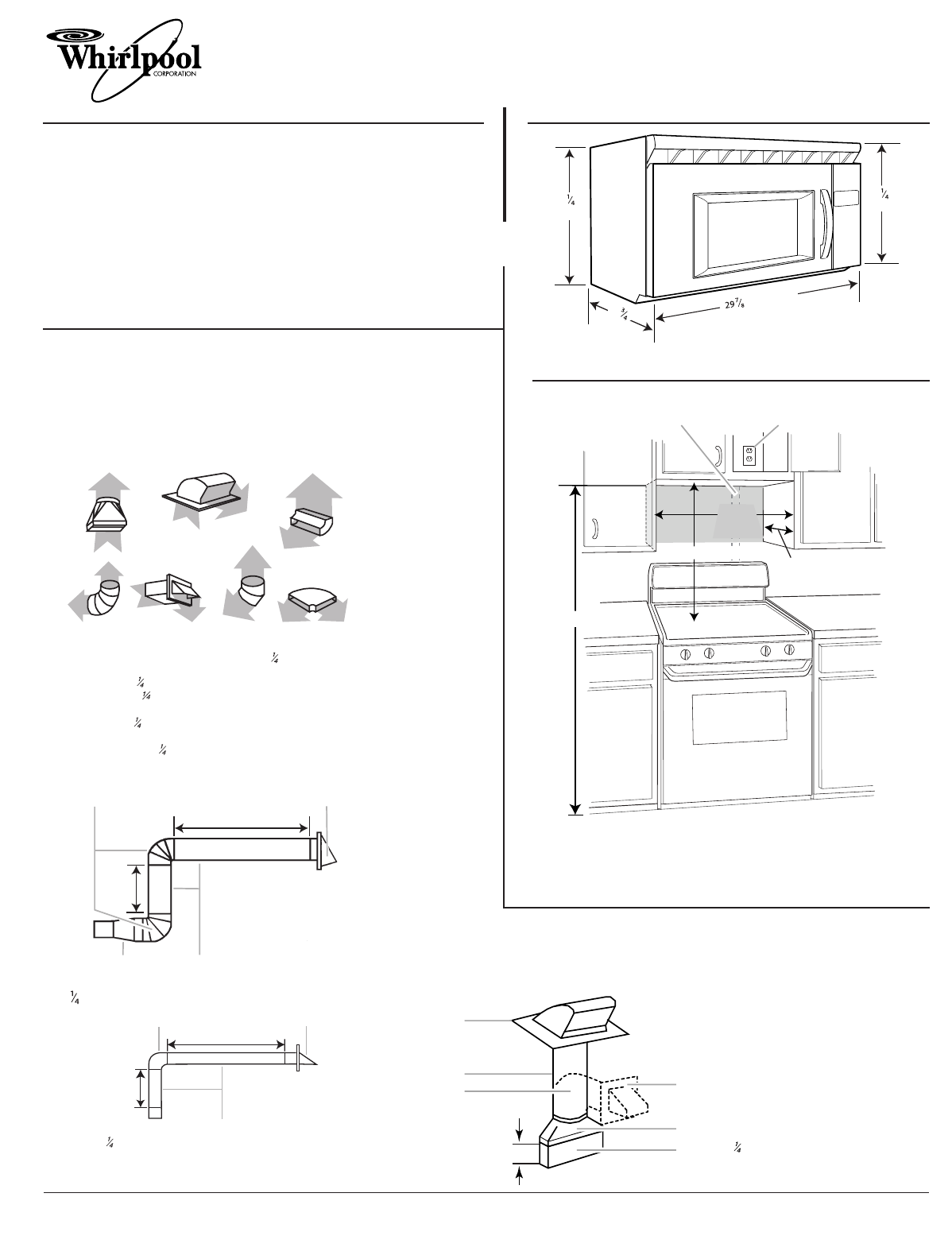
CABINET OPENING DIMENSIONS
A 3¹⁄₄" x 10" (8.3 x 25.4 cm) rectangular or 6" (15.2 cm) round vent should be used.
The total length of the vent system including straight vent, elbow(s), transitions and wall
or roof caps must not exceed the equivalent of 140 ft (42.7 m) for either type of vent.
For best performance, use no more than three 90° elbows.
To calculate the length of the system you need, add the equivalent length for each vent
piece used in the system. See the following examples:
The grounded 3-prong outlet must be inside the upper cabinet.
*30" (76.2 cm) is typical for 66" (167.6 cm) installation height.
Exact dimensions may vary depending on type of range/cooktop
below.
A.2" x 4" wall stud
B.Grounded 3-prong outlet
66" (167.6 cm) min.
12" (30.5 cm) min.
14" (35.6 cm) max.
A B
30" (76.2 cm) typical*
30"
(76.2 cm)
min.
A.Rectangular to round transition piece: 3
" x 10" to 6" = 5 ft
(8.3 x 25.4 cm to 15.2 cm = 1.5 m)
B.Roof cap: 3
" x 10" = 24 ft (8.3 x 25.4 cm = 7.3 m)
C.90° elbow: 3
" x 10" = 25 ft (8.3 x 25.4 cm = 7.6 m)
D.90° elbow: 6" = 10 ft (15.2 cm = 3 m)
E.Wall cap: 3
" x 10" = 40 ft (8.3 x 25.4 cm = 12.2 m)
F. 45 ° elbow: 6" = 5 ft (15.2 cm = 1.5 m)
G.90° flat elbow: 3
" x 10" = 10 ft (8.3 x 25.4 cm = 3 m)
A B C
D E F G
3 " x 10" (8.3 x 25.4 cm) vent system = 73 ft (22.2 m) total
A.One 3 " x 10" (8.3 x 25.4 cm) 90° elbow = 25 ft (7.6 m)
B.1 wall cap = 40 ft (12.2 m)
C.2 ft (0.6 m) + 6 ft (1.8 m) straight = 8 ft (2.4 m)
A B
C
6 ft (1.8 m)
2 ft
(0.6 m)
®
Rectangular to Round Transition for Roof Venting
NOTE: The minimum 3" (7.6 cm) clearance must exist between
the top of the microwave oven and the rectangular to round
transition piece so that the damper can open freely and fully.
A
B
C
E
F
D
3" (7.6 cm)
A.Roof cap
B.6" (15.2 cm) min. diameter round vent
C.Elbow (for wall venting only)
D.Wall cap
E.3
" x 10" to 6" (8.3 x 25.4 cm to 15.2 cm)
rectangular to round transition piece
F. Vent extension piece, at least 3" (7.6 cm) high
GMH3174XV MH1160XS WMH1162XV
GMH3204XV MH1170XS WMH1164XV
GMH5184XV MH1171XV WMH2175XV
GMH6185XV MH2175XS WMH2205XV
WMH3205XV