WINEGARD
®
Installation Instructions
Models DS-1111, VM-1111
INSTALLATION OF THIS MOUNT NEAR POWER LINES IS DANGEROUS. FOR YOUR
SAFETY, FOLLOW THE INSTALLATION INSTRUCTIONS.
STEP 1. Assemble satellite dish and mount per
manufacturers instructions. Do not make fine tun-
ing adjustment at this time.
STEP 2. Remove (2) clamp tightening carriage
bolts from existing clamp bracket.
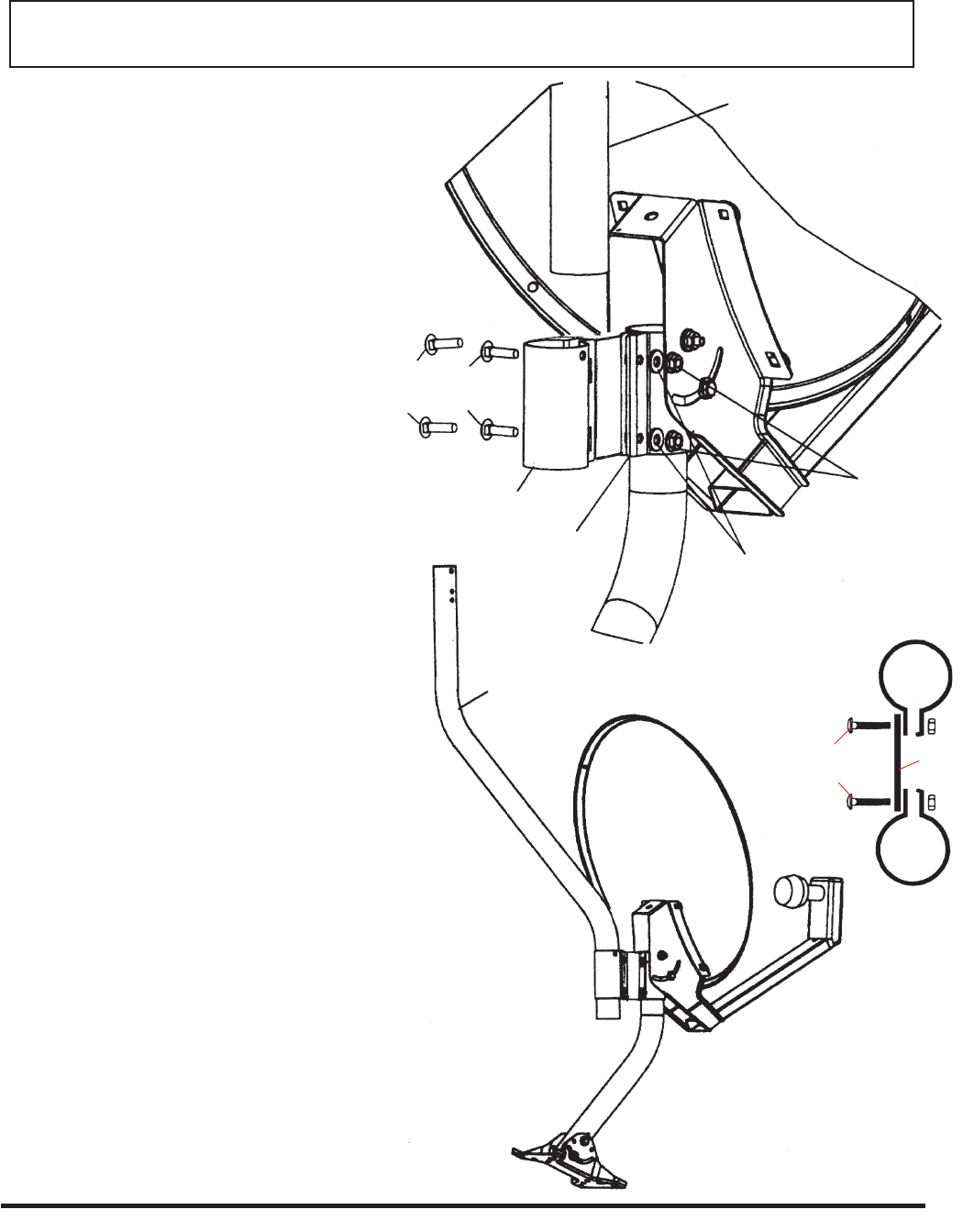
STEP 3. Attach flat plate to existing clamp bracket
with 1/4 - 20 x 1.25” bolts and install the washers
and nuts.
STEP 4. Adjust azimuth and elevation on satellite
dish for optimum signal strength per manufactur-
ers instructions.
STEP 5. Tighten all hardware on satellite antenna
mount, including clamp bolt nuts, when the opti-
mum signal strength is achieved.
STEP 6. Slide S-pipe into new clamp, and adjust
to the approximate desired location. See Figure 2
for complete assembly.
STEP 7. Mount off-air antenna to upper mast. Run
coax downlead and secure it at the same time the
DSS wires are installed.
MAKE SURE TO GROUND BOTH ANTENNA/
MOUNTS PER SATELLITE AND OFF-AIR AN-
TENNA INSTALLATION INSTRUCTIONS.
Figure 1
Figure 2
S-PIPE
S-PIPE
CARRIAGE BOLTS
1/4-20 x 1.25”
NEW CLAMP
BRACKET
EXISTING
CLAMP
BRACKET
1/4” WASHERS
1/4-20
HEX NUTS
WINEGARD
®
Printed in U.S.A. Winegard Company • 3000 Kirkwood Street • Burlington, IA 52601-2000 © Winegard Company 2001 2451765 Rev. 1/04
NOTE: THIS MOUNT IS NOT DESIGNED FOR
APPLICATIONS ON A VERTICAL SURFACE
SUCH AS WALLS, POLES, ETC.
CAUTION: LIMIT SIZE OF TV ANTENNA TO
GS-1000/2000, MS-1000/2000 OR A BOOM
LENGTH OF 40” OR LESS.
CARRIAGE BOLTS
1/4-20 x 1.25”
EXISTING
CLAMP BRACKET
FLAT
PLATE
NEW CLAMP
BRACKET
