


Manual 2100-279
Page 10
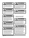
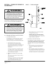
FIGURE 8
SECTION 7 • AIR CONDITIONING START
UP PROCEDURE CRANKCASE HEATERS
Single and three phase models have an insertion well-type
heater located in the lower section of the compressor
housing. This is a self-regulating type heater that draws
only enough power to maintain the compressor at a safe
temperature.
Some form of crankcase heat is essential to prevent liquid
refrigerant from migrating to the compressor, causing oil
pump out on compressor start-up and possible valve failure
due to compressing a liquid.
The decal in Figure 7 is affixed to all outdoor units detailing
start-up procedures. This is very important. Please read
carefully.
SECTION 8 • FRESH AIR DAMPER
ASSEMBLY
The fresh air damper assembly permits outside fresh air to
be introduced to the building whenever the main unit
comfort air blower is operating. The damper blade may be
set to one of four positions: 1) full open, 2) 50% open, 3)
full closed, or 4) automatic (barometric) operation. In the
latter set-up the damper blade will open and close as the
main comfort air blower cycles on and off. Reference Figure
8 for details on damper positions.
There is also a cleanable filter installed at the bottom
opening of the fresh air damper that requires periodic
cleaning. The cleaning interval will be dependent upon
frequency of unit operation and local air conditions. See
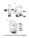
Figure 3 for Fresh Air Damper and filter locations.
MIS-957
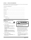
FIGURE 7
IMPORTANT
These procedures must be followed at
initial start-up and at any time power has
been removed for 12 hours or longer.
To prevent compressor damage which
may result from the presence of liquid
refrigerant in the compressor crankcase.
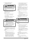
1. Make certain the room thermostat is in
the “off” position (the compressor is not
to operate).
2. Apply power by closing the system
disconnect switch. This energizes the
compressor heater which evaporates the
liquid refrigerant in the crankcase.
3. Allow 4 hours or 60 minutes per pound
of refrigerant in the system as noted on
the unit rating plate, whichever is greater.
4. After properly elapsed time, the
thermostat may be set to operate the
compressor.
5. Except as required for safety while
servicing—
Do not open system
disconnect switch.
7961-061
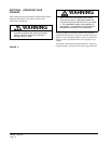
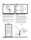
FIGURE 5
FIGURE 6
OUTER
CONE
INNER
CONE
HEAT
EXCHANGER
SECTION
NO LIFTING AWAY
FROM BURNER
PORTS
GROUND
STRAP
SENSOR
IGNITER
MIS-1067
FLAME SHOULD
ENGULF SENSOR
FULL OPEN
NORMAL BAROMETRIC
POSITION
50% OPEN FIXED POSITION. (2)
ADDTIONAL CANOE CLIPS ARE
TAPED TO THE INSIDE OF
DAMPER ASSEMBLY
TOTALLY CLOSED
POSITON