


A Product of GE Industrial Systems
General Electric Company
830 West 40
th
Street, Chicago, IL 60609 USA
773 299-6600, Fax: 630 850-6899
www.geindustrial.com
g
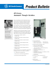
GE Zenith Controls
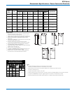
ZTS Series
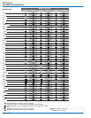
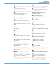
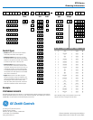
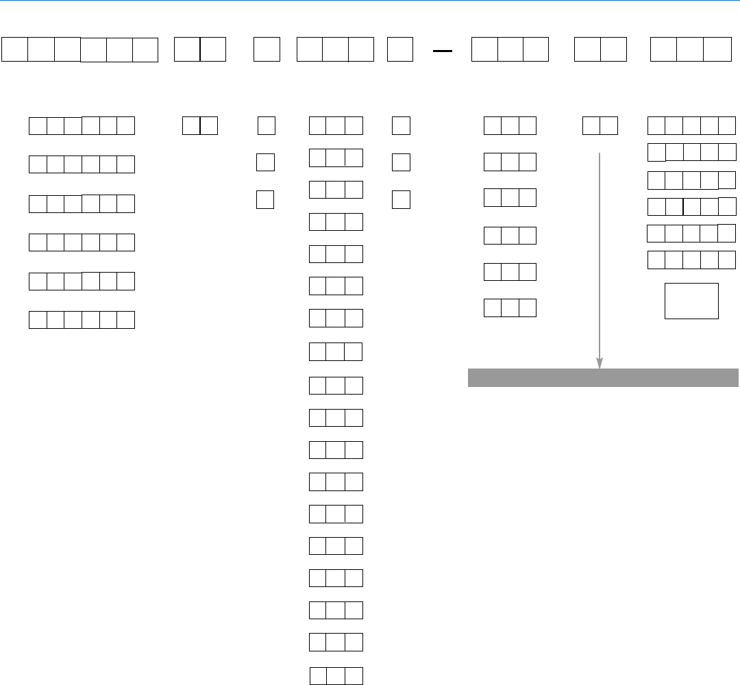
Ordering Information
Model/Type
Ampere
Size
Switched
Poles
Enclosure
Type
Operational
Voltage
Accessories
A
B
Consult Table Below
0
4
40 amps
N
Type 1 Enclosed
Open Style Unit
B
2 Poles
F
4 Poles
E
3 Poles
B 0
Entelli-Switch 250
Microprocessor
Control Unit
Standard (Open Transition)
Z
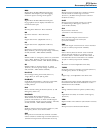
Example
ZTSCT0B0040F-N0140STD
This number string shows the correct format for a
ZTS Model Automatic Transfer Switch with closed transition,
an Entelli-Switch 250 microprocessor control unit, Utility - Generator, 400 amps, 4 pole,
NEMA Type 1 enclosure,
120/208V 3Ø, 4 wire, 60 Hz system with the standard group of accessories.
T
D
S
M
X
E
E
B 0
Control
Panel
Switch Types
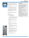
• Standard: Unless otherwise noted, the standard
switch with quick transfer will be supplied.
• Delayed Transition: When ordered as the ZTSD,
the delayed transition switch offers time delay during
transfer from one position to the other. This is primarily
for transfer of large motor or inductive loads.
• Closed Transition: When ordered as the ZTSCT,
the closed transition switch offers two basic modes
of operation. During a failure of one source or an out
of specification condition, the ZTSCT Model operates
as a standard delayed transition switch (
ZTSD Model).
This sequence allows clear separation of an unreliable
source from an available one.
• Bypass: When ordered as the ZBTS, the bypass
transition switch offers a draw-out mechanism, with
electrical and mechanical interlocks for secure removal
after load bypass. In this way the transfer switch
and/or the control panel may be tested, isolated and
removed for maintenance without load interruption.
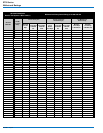
Then choose
additional
accessories
0
0
8
80 amps
0
1
0
100 amps
0
1
5
150 amps
0
2
0
200 amps
0
2
2
225 amps
0
260 amps
4
0
400 amps
0
6
0
600 amps
0
8
0
800 amps
0
0
0
1000 amps
1
2
0
1200 amps
1
6
0
1600 amps
1
0
0
2000 amps
2
6
0
2600 amps
2
0
0
3000 amps
3
Config.
0
Utility - Generator
M
Manual
U
Utility - Utility
0
0
0
2
6
0
Type 4 Enclosure
Type 12 Enclosure
Type 4X Enclosure
Type 3R Enclosure
0 1
N
1 2
N
3 R
N
0 4
N
4 X
X
0 0
T
S
Z
Delayed Transition
0
0
D
T
S
Z
Closed Transition
T
0
C
T
S
Z
Standard (Open Transition) w/ Bypass
0
0
S
B
T
Z
Delayed Transition w/ Bypass
D
0
S
B
T
Z
Closed Transition w/ Bypass
C
T
S
B
T
Z
3
0
300 amps
0
0
0
4000 amps
4
O
N
C
E
N
S
P
E
S
S
G
P
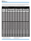
A B Voltage Phase Config. Hz
1 0 120 1 2 wire 60
2 0 120/240 1 3 wire 60
2 1 120/208 3 3 wire 60
3 0 240 3 3 wire 60
3 1 208 3 3 wire 60
3 2 220 3 3 wire 50
3 3 120/240 3 4 wire 50
3 4 110/220 3 4 wire 60
3 5 139/240 3 4 wire 60
3 8 120/240 3 4 wire 60
4 0 120/208 3 4 wire 60
4 1 127/220 3 4 wire 60
4 2 127/220 3 4 wire 50
5 0 480 3 3 wire 60
5 1 440 3 3 wire 60
5 2 440 3 3 wire 50
5 5 460 1 3 wire 50
5 7 480 1 2 wire 60
5 8 254/440 3 4 wire 60
6 0 575 3 3 wire 60
6 1 347/600 3 4 wire 60
7 0 277/480 3 4 wire 60
7 1 277 1 2 wire 60
7 4 266/460 3 4 wire 60
7 5 460 3 3 wire 60
8 0 120/240 2 4/5 wire 60
8 2 380 1 2 wire 50
9 0 240/416 3 4 wire 60
9 1 220/380 3 4 wire 60
9 2 220/380 3 4 wire 50
9 3 240/416 3 4 wire 50
9 7 380 3 3 wire 60
Note: Operating voltage must be specified at time of order.
Only the most common voltages are shown above.
S
M
S
M
S
M
S
M
S
M
S
Contents contained in this document are subject to
change without notice. Contact GE to verify details.