


5
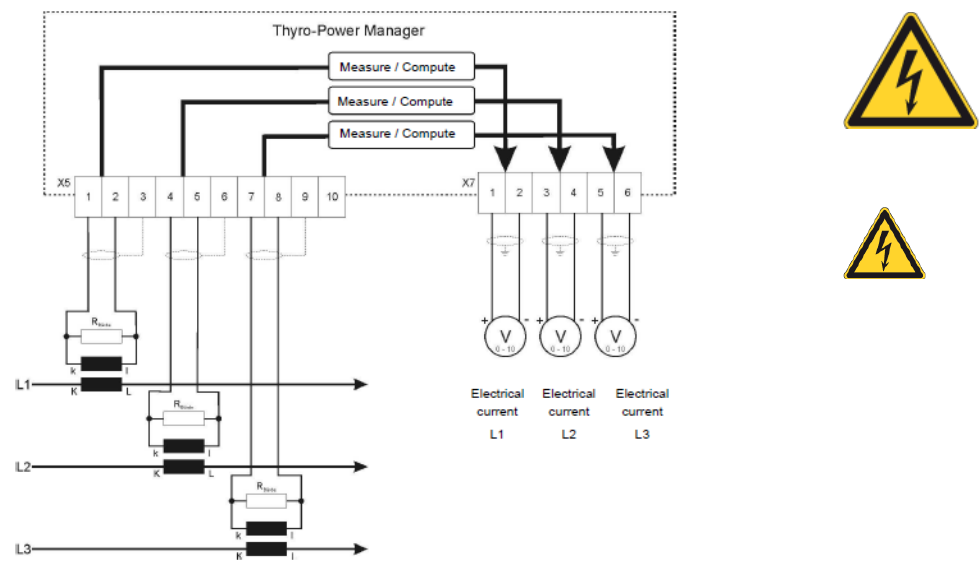
The load resistance also has to be connected externally to the current converters. Within
standard default setting the following measurement values are read out: output 1 -
measurement value 1, output 2 - measurement value 2, output 3 - measurement value 3.
The following figure displays the principle structure and the connection diagram if using as
additional measurement device.
Figure 5: Connection Diagram for Additional Measurement Device
3.2. SETTING THE NETWORK PEAK LOAD MONITORING /
MEASUREMENTS:
No settings are necessary for the additional measurement device. Converters or load
resistances have to be configured in a manner so that a 1V~ measurement voltage is
generated at a nominal electrical current. Thus, a voltage of 10V- results at the respective
analog output.
3.3. SETTING THE LIMITING VALUE FOR MONITORING
If the additional measurement device is also used as network peak load monitoring, limiting
value could be set via the help of the potentiometer R310. Standard setting is 200%, the
6
potentiometer is set on right stop, whereby 100% meaning 1V~ at the measurement inputs /
load resistances.
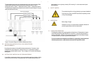
4. SAFETY NOTES
The commissioning of the unit is permitted only upon expert installation!
For this see the currently valid AEG Power Solutions operating manual
of Thyro-Power Manager.
5. OPERATION
Mains voltage - Danger!
Activate the unit only if it is secured that all necessary measures for
protection against electric shock are implemented.
5.1. REGULAR OPERATION
Enabling mains voltage during regular operation activates the unit. Subsequently, the green
power LED H100 and the green ON LED H101 should burn. If network load optimization is
used, the LEDs H201 - H210 turn ON one after another (contingent to the selected number).
All measurements and functions are performed as selected.
For more information and integration of software for programming, measurement and
indication please see our comprehensive and actual valid operations manual.