


Instructions for the installer
12.2.3 Replacing the electric cable
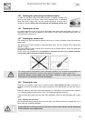
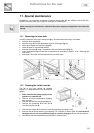
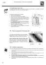
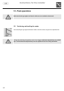
To replace the electric cable, it is necessary to access the terminal board. It is located on the back
of the appliance, at the top left, as shown in the figure.
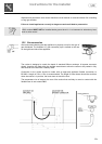
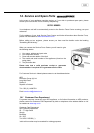
To replace the cable, proceed as follows:
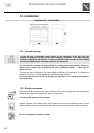
• open the terminal board box;
• unscrew the screw
A
that locks the cable;
• loosen the screw contacts and replace the cable
with one of the same length that corresponds to the
specifications in the table in section “12.2.1 Electric
power cable section”;
• the "
yellow-green
" earth wire must be connected to
the terminal
and must be approximately
20 mm
longer than the line cables;
• the neutral "
blue
" wire must be connected to the
terminal marked with the letter
N
;
• the live "
brown
" must be connected to the terminal
marked with the letter
L
.
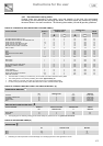
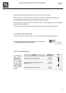
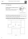
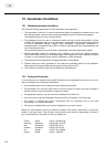
12.3 Power consumption of the ceramic hob
The ceramic hob has different power consumptions
depending on the type of heating element used. The
diagram shows the values of the power consumed.
In the envisaged cases, the first numeric value
refers to the total power, whereas the value that
follows the symbol "
/
" refers to the inside diameter,
with the exception of the central heating element,
whose value that follows "
/
" refers to the outer
diameter.
12.4 Ventilation requirements
The room containing the appliances should have an air supply in accordance with B.S. 5440 part 2.
1. All rooms require an opening window or equivalent, and some rooms will require a permanent
vent as well.
2. For room volumes up to 5m³ an air vent of 100cm² is required.
3. If the room has a door that opens directly to the outside, and the room exceeds 1m³ no air
vent is required.
4. For room volumes between 5m³ and 10m³ an air vent of 50cm² is required.
5. If there are other fuel burning appliances in the same room B.S. 5440 part 2 should be
consulted to determine the air vent requirements.
6. The appliance must not be installed in a bed sitting room of less than 20m or in a bathroom or
shower room.