


7
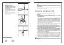
Starting up and temperature regulation
Wash the inside of the appliance with lukewarm water with a little bicar-
bonate of soda added (5ml to 0,5 litre of water). Do not use soap or deter-
gent as the smell may linger. Dry the appliance thoroughly.
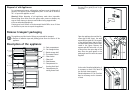
• When the refrigerator compartment door is opened, the internal lighting
is switched on. The temperature control knob is located on the right hand
side of the refrigerator compartment.
Setting “0”: Off.
Setting “1”: Hightest temperature, (warmest setting).
Setting “6” (end-stop) : Lowest temperature, (coldest setting).
The exact setting should be chosen keeping in mind that the temperature
inside the refrigerator depends on:
-the quantity of food stored
-how often the door is opened
The temperatures in the refrigerator compartment and freezer compart-
ment cannot be independently regulated.
If you want to freeze fresh food rapidly, select setting “6”, ensuring that the
temperature in the refrigerator compartment does not drop below 0°C. You
should reset the temperature control knob to setting “3” or “4”, if this does
occur.
As soon as the fresh food placed in the freezer has frozen, return the tem-
perature control knob to “3” or “4”.
Important!
High ambient temperatures (e.g. on hot summer days) and a cold setting on
the temperature regulator (position"5" to "6") can cause the compressor to
run continuously.
If this happens, turn the temperature
regulator back to a warmer setting
(position "3" to "4"). At this setting
the compressor will be switched on
and off as usual and automatic
defrosting recommenced.
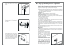
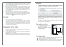
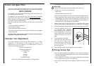
Ambient Temperature switch
With a room temperature below
+16°C the Fridge freezer may not
function correctly. If the room tem-
perature is lower than +16°C it will
be necessary to depress switch (A).
The relevant pilot light comes on.
D710
A
22
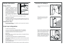
D726
B
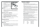
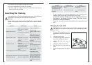
Apply covers (B) into the relevant
holes.
Place guide (A) on the inside part of
the furniture door, in the upper and
lower positions as shown in the fig-
ure and mark the position of external
holes. having drilled the holes, fix the
guide with the screws supplied.
20 mm
A
50mm
PR166
Separate parts A, B, C, D as shown in
the figure
PR266
A
B
C
D