


file:///D:/System/DATA/Dx/ds1/Us/iss1/EINS512426/EINS512426.htm
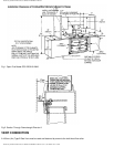
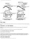
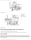
1. Isolate the gas supply by turning off the service gas valve beneath the combination gas valve. Break the hexagon union
connection nut. (See
Fig. 7).
2. Detach inner burner fixing screws (See
Fig. 7) and draw complete gas burner assembly clear of the combustion chamber
resting it on the floor in front of the range.
NOTE: THERE IS SUFFICIENT LENGTH OF THERMOSTAT CAPILLARY TUBE WITHOUT DETACHING THE SENSING END
FROM THE TOP OF THE ROASTING OVEN.
3. Remove the boiling plate, combustion chamber baffle and simmering plate.
4. Check conditions of flueways and combustion chamber and clean if necessary.
5. Lightly brush the perforated top of the gas burner and check that the burner venturi is free of lint and fluff.
NOTE: IT MAY BE NECESSARY TO DETACH THE PILOT ASSEMBLY AND REMOVE THE BURNER TO ENSURE IT IS FREE.
6. Check the condition of the pilot thermocouple tip to ensure it is clean and free of carbon. Heavy heat oxidised tips should mean
the removal of the thermocouple and a new replacement. Examine and brush clean the pilot light parts and examine the ignitor
cable and connector strip to ensure the PTFE insulation cable, remains intact and strip is firmly connected to the spark electrode.
Clean any carbon away from the electrode.
7. Refit combustion burner chamber baffle.
8. Refit gas burner assembly in reverse manner described in 2 and reconnect gas supply at service gas valve union. On
completion test the gas installation for soundness and purge. Leak testing of the appliance shall be conducted according to
manufacturers instructions. NOTE: USE SOAPY WATER SOLUTION ON NEW GAS CONNECTIONS TO ENSURE THERE ARE
NO GAS LEAKS.
9. Turn on the gas supply and follow the procedure for lighting the burner.
10. Ensure that the pilot and main burner flames are burning evenly, the thermocouple is enveloped by the pilot flame.
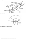
11. Visually check main burner and pilot flame for correct flame pattern. An established main burner at high fire will be
predominantly blue with yellow tippings on an even height flame strip and be about 150mm (6in) high. See
Fig. 6. Ensure all
flameports have cross-lit and that the pilot light flame is free from sooting.
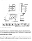
12. The maximum depth of any cabinets installed above the top cooking surface of the range must not exceed 330mm (13in).
For further advice or information contact your local distributor/stockist
With Aga’s policy of continuous product improvement, the Company reserves
the right to change specifications and make modifications to the appliance described and illustrated at any time.
file:///D:/System/DATA/Dx/ds1/Us/iss1/EINS512426/EINS512426.htm (10 of 11)8/17/2006 10:51:16 AM